3-21
4 If stop entering a value, put the cursor on Close and then left-click
the button.
The latitude/longitude input screen will close without reflecting the set value to the
operating state.
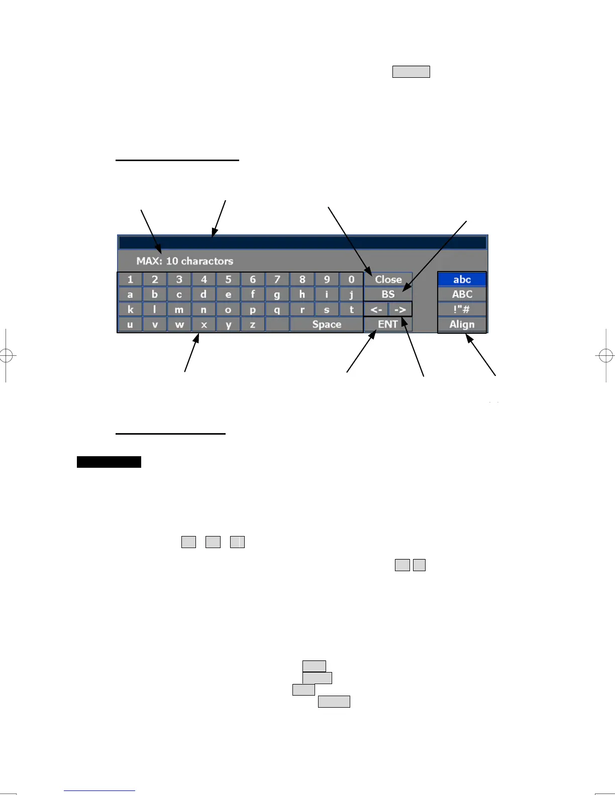
Character input screen
Entering a character
Procedures 1 On the character input screen, use trackball to select alphabet from A to
Z, numbers from 0 to 9, or symbols (only comments for mark/line), and
then left-click the character button to enter one character of the name to
be inputted.
For example, input「abc」, left-click button as follows:
a → b → c
2 When wanting to shift entry position, move in <- , -> button.
Or, left-click a cursor according to the entry position of entered
character.
The | cursor blinks to the entry position.
3 When changing a type in character, left-click input character change
button
Input lowercase: Left-click the abc button.
Input uppercase: Left-click the ABC button.
Input symbol: Left-click the !”# button.
Arrangement dialog: Left-click the Align button.
・As for the arrangement dialog version, only lowercase and uppercase become valid
Enter
ボタン
Back Space
ボタン
文字/数字/記号
ボタン
Close
ボタン
入力位置移動
ボタン
最大文字入力数
入力文字切替
ボタン
入力文字表示エリア
Enter button
Character/numeric/symbol button
Entered character
Close button
Maximum inputting characters
Back Space
button
Inputting character
change button
Inputting position
shift button

 Loading...


