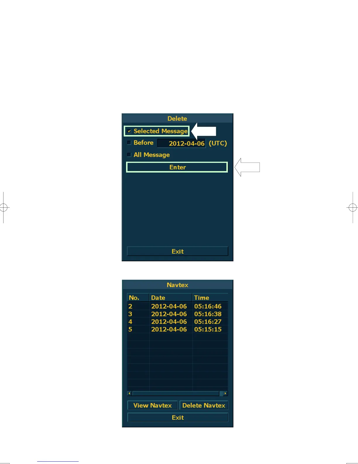
Home
JRC
Marine Radar
JMA-932B-SA
JRC JMA-932B-SA User Manual
5
of 1
of 1 rating
486 pages
Give review
Manual
Specs
To Next Page
To Next Page
To Previous Page
To Previous Page
Loading...
3-87
・
Selected Message
…
Deleting selected
message
・
Before
…
Del
eting the messages before the
input date
(
Date input is needed
)
・
All Message
…
Deleting all messages
(1)
In case of deleting selected message
Check “
Selected Message”, and left-click Enter button.
Selected message will be deleted.
193
195
Table of Contents
Preface
7
Before Operation
8
Precautions
9
Equipment Appearance
20
Glossary
25
Table of Contents
31
Section 1 General and Equipment Composition
44
Functions
44
Function of this System
44
Features
45
Performance Monitor
46
Configuration
47
Exterior Drawings
49
General System Diagrams
65
Section 2 Names and Functions of Control Panel Keys
73
Names of Display
74
Names and Functions of Control Panel Keys
84
Functions of Software Buttons
89
Chart Menu
103
Main Menu
103
Section 3 Basic Operation 3.1 Operation Flow
107
Section 3 Basic Operation
108
Operation Flow
108
Power on and Start the System
109
3.1.2 Observe and Adjust Video
111
Acquire and Measure Data
111
Display and Measure with Reference to CCRP
111
End the Operation and Stop the System
112
Observe and Adjust Video
113
Adjust Monitor Brilliance [BRILL]
113
Change Observation Range [RANGE+/-]
113
Tune
114
Adjust Gain [GAIN]
115
Suppress Sea Clutter [SEA]
116
Suppress Rain/Snow Clutter [RAIN]
118
Reset Alarm Buzzer [ALARM ACK]
119
Adjust to the Best Image
120
Operation Procedures
121
Move Cross Cursor Mark by Trackball
121
Operate Software Buttons
121
Operation of Combobox
122
Operation of Checkbox
122
Basic Menu Operation
123
Operation on Numeric Value, Latitude / Longitude and Character Input Menu
125
Overview of Menu Structure
130
General Radar Operations
131
Interference Rejection (IR)
131
Switch Transmitter Pulse Length [GAIN]
132
Target Enhance (ENH)
132
Use Video Processing (PROC)
133
Switch Azimuth Display Mode (AZI Mode)
134
Switch True/Relative Motion Display Mode (TM/RM)
135
Move Own Ship's Display Position (off Center)
136
Display Radar Trails (Trails)
137
Zoom (X2)
140
Hide/Display Range Rings (HL Off)
140
Hide Graphics Information on Radar Display (Data Off)
141
Switch Day/Night Mode [DAY/NIGHT]
141
Adjust Operation Panel Brilliance [PANEL]
141
3.4.14 Set True Bearing
142
3.4.15 Set Own Ship Speed
142
3.4.15.1 Switch Own Ship Speed Device
142
Input the Own Ship Speed (Manual Speed)
143
3.4.16 Set Drift Correction
144
Use Own Ship's Track Data
145
Set Display Color of Own Ship's Track (DISP Own Track Color)
145
Save Own Ship's Track Data
146
Cancel Saving of Own Ship's Track Data (Own Track Memory)
146
Clear Own Ship's Track Data (Clear Own Track)
146
Use Expanded Own Ship's Track (Own Track Type)
147
Use Water Depth Track (Water Depth Setting)
148
Use Water Temperature Track (Water TEMP Setting)
149
Use Current Track (Current Setting)
150
Loading and Saving of Own Track (File Operation)
151
Display User Map
153
Create User Map (Mark/Line)
153
3.6.1.1 Plotting a Mark
153
3.6.1.2 Plotting a Line
154
3.6.1.3 Input Latitude Longitude and Draw Mark/Line
155
Set User Map Display (Mark Display Setting)
156
Edit User Map (Edit User Map)
158
Correct Position on User Map (Shift User Map)
165
User Map File Operation
166
Use Route Function
169
Display Route
169
3.7.2 Use Route Monitoring Function
170
Applied Operations
171
Set Radar Signal Processing (Process Setting)
171
Set Radar Trails (RADAR Trails Setting)
173
Set Scanner Unit (TXRX Setting)
175
Set Own Ship Mark (Own Ship Setting)
176
Setting of Danger Detection (Danger Detection Setting)
177
Monitoring Dragging Anchor (Anchor Watch)
178
MOB (man over Board)
179
Set Radar Display (Display Setting)
180
Adjust Sound Volume (Buzzer Volume)
182
3.8.10 Screen Capture Setting
183
Set User Option Keys [OPTION 1/2]
184
Set Navigation Data Display (Multi Window Setting)
186
3.8.13 Setting of NAVTEX Message Display
191
Use Function Key
198
Operation Procedures
198
Use Function Key [User]
198
Function Setting Menu Items
199
Overview of Function Operations (User Function Setting)
200
Overview of Saved Function Setting Data
203
Use User Setting
204
Save Operating State (Save User Setting)
204
Load Operating State (Load User Setting)
205
Delete Operating State (Delete User Setting)
205
Using File Manager
206
Operate File on the Card (File Manager)
207
Using Chart
210
3.12.1 Displaying the Chart
210
The Setting of the Chart Object to Display (Chart Menu)
210
The Display of the Information of Chart Published (ENC Issue Status)
211
The Setting of Contour (Contour Setting)
211
The Setting of Chart Type (Chart Type)
212
Changing Operation Mode
213
3.13.1 Changing to ECDIS Mode from RADAR Mode
213
3.13.2 Changing to RADAR Mode from ECDIS Mode
213
Section 4 Measurement of Range and Bearing
215
Use of Navigation Tools
216
Using Cursor (Cursor)
217
Using Range Rings (Range Rings)
217
Using Electronic Bearing Lines (EBL1/EBL2)
218
Using Variable Range Marker (VRM1 / VRM2)
222
Using Parallel Index Lines (PI Menu)
224
Operating EBL Maneuver Function (EBL Maneuver Setting)
230
Operating EBL, VRM, and PI with Cursor
232
Measurement of Range and Bearing
235
Measurement with Cursor Position (Cursor)
235
Measurement with Electronic Bearing Line and Variable Range Marker [EBL] [VRM]
237
Measurement with Two Arbitrary Points
238
Section 5 Operation of Target Tracking and Ais 5.1 Preparation
239
Section 5 Operation of Target Tracking and Ais
241
Preparation
241
Target Tracking Function
241
Collision Avoidance
242
Basic Concept of Collision Avoidance
243
Radar and Collision Avoidance
244
Relative Vector and True Vector
244
Definitions of Symbols
245
Radar Display
250
Cursor Modes (Cursor)
252
Setting Collision Decision Criteria
254
Setting CPA Ring
254
Setting the GPS Antenna Location
255
Setting Vectors (Vector Time)
255
Target Tracking Operation
256
Acquiring Target [ACQ]
256
Canceling Unwanted Tracked Targets [ACQ CANCEL]
258
Tracked Target Data Display [TGT DATA]
259
Displaying Target ID No. (Target Number Display)
260
Adding Tracked Target ID Name (Name)
261
Reference Target (Reference)
262
Operation Test (TT Test Menu)
264
Ais Operation
269
Restrictions
269
Setting AIS Display Function (AIS Function)
269
Activate AIS Targets (Activate AIS)
270
Deactivate AIS Targets (Deactivate AIS)
270
Displaying AIS Information [TGT DATA]
271
Displaying Target ID No. (Target Number Display)
275
Setting AIS Filter (AIS Filter Setting)
275
Conditions for Deciding AIS Target to be Lost
278
Setting Conditions for AIS Alarm (AIS Alarm Setting)
279
DECISION of TARGETS as IDENTICAL (Association)
280
Alarm Display
283
Lost Target Alarm
286
Gyro Set Alarm
287
Track Function
288
Past Position (Past POSN)
288
Target Ship's Tracks (Target Track)
289
File Operations
294
Trial Maneuvering (Trial Maneuver)
298
Trial Maneuvering in the True Vector Mode
299
Trial Maneuvering in the Relative Vector Mode
300
Operation of Trial Maneuvering Function
301
Section 6 True and False Echoes on Display 6.1 Radar Wave with the Horizon
303
Section 6 True and False Echoes on Display
304
Radar Wave with the Horizon
304
Strength of Reflection from the Target
306
Sea Clutter and Rain and Snow Clutter
308
False Echoes
312
Display of Radar Transponder (Sart)
315
Display of Radar Transponder(Sart)
315
Display of Ais-Sart
317
Section 7 Settings for System Operation 7.1 Settings at Installation
319
Section 7 Settings for System Operation
320
Settings at Installation
320
How to Open the Serviceman Menu
320
GYRO I/F Setting
321
Tuning (Tune Adjustment)
323
Tune Indicator Adjustment
323
Bearing Adjustment
324
Range Adjustment
324
Setting of True Bearing Value
325
Antenna Height Setting (Antenna Height)
325
Setting of CCRP (CCRP Setting)
326
7.1 Settings at Installation
327
Settings
328
Sector Blank Setting (Sector Blank)
328
7.2 Settings
329
Setting of Bearing Pulses from Antenna (Output Pulse)
330
Slave Mode Setting (Master/Slave)
330
Date Time Setting
331
Data Path(Data Path Setting)
332
Input Installation Information
333
Setting the Alarm System (Alarm)
334
INS Setting
337
Setting of Transferring Track
338
Adjustment
339
Adjustment of Target Tracking Function (TT)
340
Main Bang Suppression Level Adjustment (MBS Level)
342
Adjustment of Performance Monitor (MON)
343
7.3 Adjustment
345
Maintenance Menu
346
Initialization of Memory Area (Area Initial)
346
Save of Internal Memory Data
347
Restoration of Antenna Operation Time (TXRX Time)
353
Section 8 Maintenance
356
Routine Maintenance
356
Regular Backup
357
Maintenance on each Unit
360
Scanner Unit NKE-1125/1129/1130/1139
360
Wave Guide Tube (JMA-923B-7XA/9XA)
363
Coaxial Cable (JMA-933B-SA)
363
Transmitter-Receiver Unit NTG-3225/3230
363
Display Unit NCD-2096
364
Performance Check
365
Check Performance on Test Menu
366
Monitor Test
369
Magnetron Current
370
System Alarm Log Display
371
System Info
371
Replacement of Major Parts
373
Parts Required for Periodic Replacement
374
Replacement of Magnetron
374
Replacement of Motor
384
Replacement of LCD Monitor
389
Replacement of Backup Battery
390
Replacement of Battery on CMC-1323(Μatx Mother Board)
390
Replacement of Battery on CBD-1831(UPS Battery)
396
Section 9 Troubleshooting and After-Sales Service
397
Fault Finding
398
List of Alarms and Other Indications
398
Operation Checking
404
Fuse Checking
404
Trouble Shooting
405
Special Parts
406
Circuit Block to be Repaired
407
9.2.3 if the USB Security Dongle Were Broken
411
Entering in the Functional Restriction Mode
411
9.2.5 if both of Hard Disk Drives (CDD-717) Were Broken
412
9.2.6 Entering in the Emergency Mode
412
After-Sales Service
415
9.3.1 Keeping Period of Maintenance Parts
415
9.3.2 When Requesting for Repair
415
Recommended Maintenance
415
Radar Failure Check List
416
Disposal of the Unit
417
Section 10 Disposal
418
Disposal of the Unit
418
Disposal of Used Batteries
418
Disposal of Used Magnetron
418
Disposal of Tr-Tube
419
ABOUT the CHINA Rohs
420
Section 11 Specifications
422
Jma-933B-Sa Type Radar
422
Jma-932B-Sa Type Radar
423
Jma-923B-7Xa/9Xa Type Radar
424
Jma-922B-6Xa/9Xa Type Radar
425
Scanner Unit (Nke-1139)
426
Scanner Unit (Nke-1130)
426
Scanner Unit (Nke-1129-7/9)
427
Scanner Unit (Nke-1125-6/9)
428
Transmitter Receiver Unit (Ntg-3225)
430
11.9 Transmitter Receiver Unit (Ntg-3230)
431
11.10 Transmitter Receiver Unit (Ntg-3225)
431
Display Unit (Ncd-2096)
431
Target Tracking Function
434
Ais Function
435
Performance Monitor (Nju-84)
436
Performance Monitor (Nju-85)
436
Appendix A
437
Interswitch Instruction Manual
437
Overview
438
Interswitch Setup
438
A.1.1 Overview
438
Interswitch Operation
440
Operation Flow
440
A.2 Interswitch Operation
440
Inter Switch Menu
441
Change of Connection Pattern
443
Operating Connection Pattern Files (ISW Pattern
444
Operating Connection Pattern
444
Name of Display Units and Scanner Units
445
Scanner Units
445
Reference
446
A.3 Reference
446
5
Based on 1 rating
Ask a question
Give review
Questions and Answers:
Need help?
Do you have a question about the JRC JMA-932B-SA and is the answer not in the manual?
Ask a question
JRC JMA-932B-SA Specifications
General
Brand
JRC
Model
JMA-932B-SA
Category
Marine Radar
Language
English
Related product manuals
JRC JMA-933B-SA
486 pages
JRC JMA-9303-CA
192 pages
JRC JMA-993-SA
407 pages
JRC JMA-9133-SA
572 pages
JRC JMA-9172-SA
486 pages
JRC JMA-9832-SA
372 pages
JRC JMA-9132-SA
572 pages
JRC JMA-9922-9XA
407 pages
JRC JMA-9252-6CA
192 pages
JRC JMA-9122-6XA
572 pages
JRC JMA-9110-6XA
572 pages
JRC JMA-9900 Series
125 pages