8-28
8 8 8
8.5 Replacement of Major Parts
yyyy
yyyy
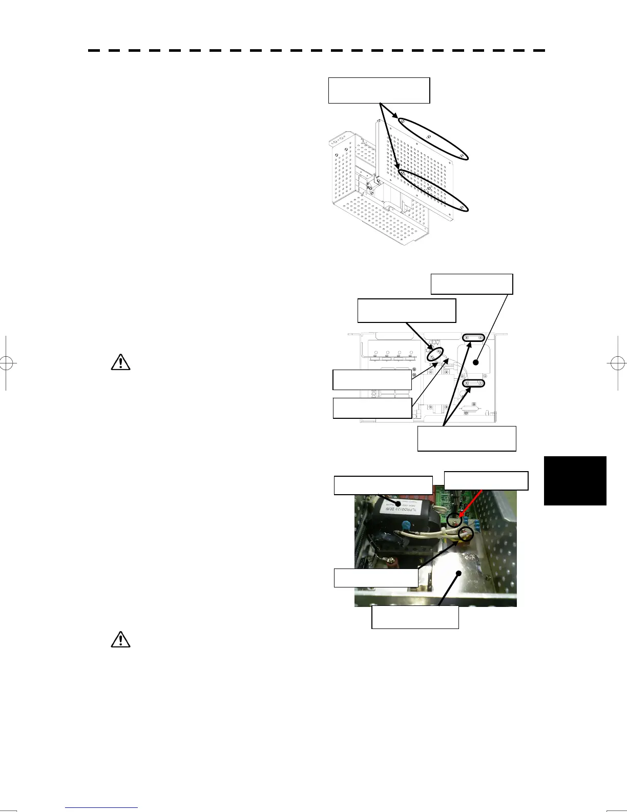
(5) Remove the screws (six M4 screws)
and take off the modulator cover.
(6) Remove the screws holding the cables
(two M4 screws) and the screws
holding the magnetron (four M4 screws)
and remove the metal fitting and the
magnetron.
Use shielded screwdrivers for the work. If a
metal object (tool) touches the magnetron, its
performance may deteriorate.
(7) Be careful to attach the colored cables
(yellow and green) to the correct
connections on the replacement
magnetron.
After having replaced the magnetron,
reassemble the unit by following the
disassembly procedure in the reverse
order.
Do not forget to tighten the bolts and
screws, and do not forget to reconnect
the cables.
Extreme care should be taken to connect the
leads (yellow and green) to the magnetron for
prevention of contact with other parts or the casing.
Contact may cause them to discharge.
(8) Turn on the radar power supply and check that the system works properly.
Magnetron
Pulse transformer
Yellow cable
Green cable
Remove the six
screws.
Remove the two
screws.
Remove the four
screws.
Magnetron
Yellow cable
Green cable

 Loading...


