13 Configuration
202
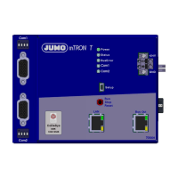
Multichannel controller module
Controller C01ManualMode to
C04ManualMode
Manual mode active for controller channel
1to4
C01TuneActive to C04TuneActive Self-optimization active for controller module
1to4
C01Output1 to C04Output1 Switch position of first controller output of con-
troller channel 1 to 4
C01Output2 to C04Output2 Switch position of second controller output of
controller channel 1 to 4
C01CollAlarm to C04CollAlarm Collective alarm of controller channel 1 to 4
(can be configured with signals from the digital
selector)
Setpoint SP01RampTolBand to
SP04RampTolBand
Alarm signal of tolerance band monitoring of
ramp function 1 to 4
SP01Changeover1 to
SP04Changeover1
Bit 0 of setpoint changeover of setpoint value
function 1 to 4
SP01Changeover2 to
SP04Changeover2
Bit 1 of setpoint changeover of setpoint value
function 1 to 4
Analog inputs AI01Alarm1 to AI04Alarm1 Alarm signal 1 of analog input 1 to 4
AI01Alarm2 to AI04Alarm2 Alarm signal 2 of analog input 1 to 4
Digital inputs DI01, DI02, DI05 to DI10 Signal of digital input 1, 2, 5 to 10
If the HW counter is activated, the signal of
digital input 1 is inactive.
Limit monitoring LI01 to LI04 Output signal of limit value monitoring 1 to 4
Mathematics Logic01 to Logic04 Result of logic function 1 to 4
Miscellaneous CollectiveAlarm Controller module collective alarm
HWCounterSignal Signal of hardware counter in "fill" operating
mode (as shut-down signal when threshold
value reached)
Category Signal Description