Front Panel Operation
3-70
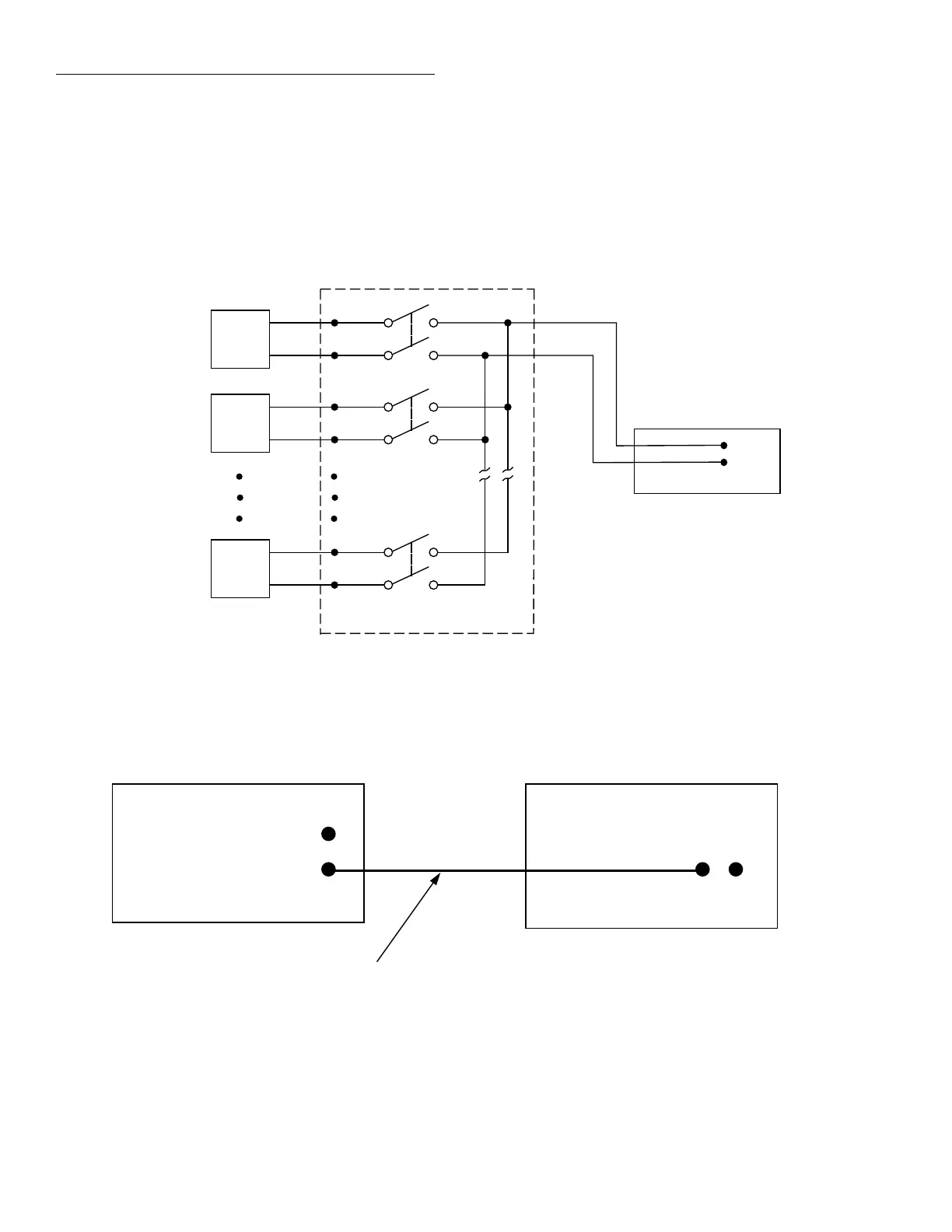
The Trigger Link connections for this test system are shown
in Figure 3-30. Trigger Link of the Model 2001 is connected
to Trigger Link of the Model 7001 Switch System. Notice
that only one Trigger Link cable is needed.
igure 3-29
UT test system
2001 Multimeter
1
DUT
#1
2
DUT
#2
10
DUT
#10
OUTPUT
Card 1
7011 MUX Card
Input HI
Input LO
igure 3-30
Trigger Link connections (asynchronous example #1)
Trigger
Link
7001 Switch System
Trigger
Link Cable
(8501)
2001 Multimeter
IN
OUT
Trigger
Link
IN OUT
Asynchronous Trigger Link example #1
In a typical test system, you may want to close a channel and
then measure the DUT connected to the channel with a mul-
timeter. Such a test system is shown in Figure 3-29, which
uses a Model 2001 Multimeter to measure ten DUTs
switched by a Model 7011 multiplexer card in a Model 7001
Switch System.