Front Panel Operation
3-36
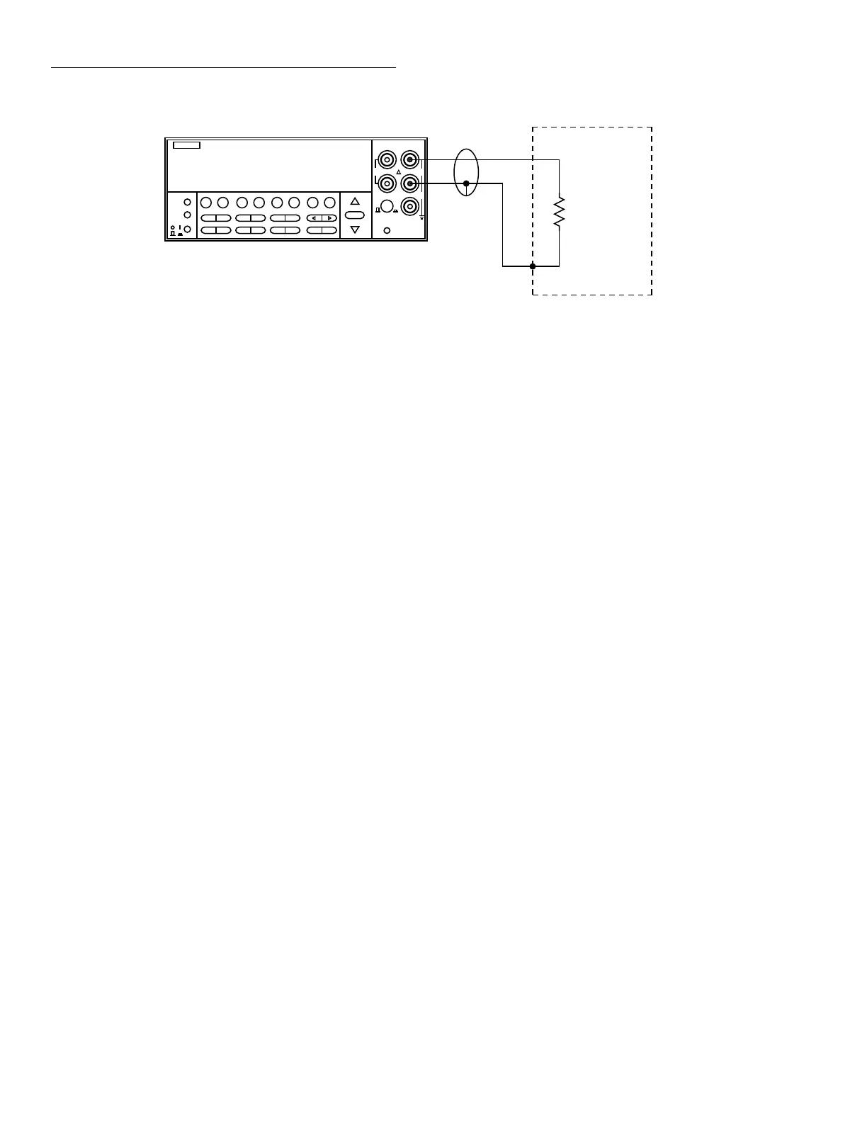
5. Connect the test leads to the resistance as shown in Fig-
ure 3-15.
CAUTION
Do not exceed 1100V peak between IN-
PUT HI and LO, or instrument damage
may occur.
6. Observe the display. If the “Overflow” message is
shown, select a higher range until a normal reading is
displayed. Always use the lowest possible range for the
best resolution.
7. Take a reading from the display.
Zeroing
The term “when properly zeroed” means that you must es-
tablish a baseline for subsequent measurements on that
range. The 20Ω and 200Ω resistance ranges require zero cor-
rection to correct for thermal offsets. This procedure should
be performed whenever the ambient temperature changes. To
zero (rel) the Model 2001, use the following procedure:
1. Disable rel, if presently enabled, by pressing the REL
key. The REL annunciator will turn off.
2. Select the desired function (Ω2 or Ω4) and range.
3. Connect the test leads to INPUT HI and LO (and
SENSE Ω4 WIRE if the Ω4 function is selected) of the
Model 2001 and short them together. Noise and thermal
offsets may require a few moments to stabilize.
4. Press the REL key. The display will read zero.
5. Remove the short and connect the test leads to the resis-
tance to be measured.
6. Observe the display. If the “Overflow” message is
shown, select a higher range until a normal reading is
displayed. Always use the lowest possible range for the
best resolution.
7. Take a reading from the display.
4-wire resistance measurements
The Model 2001 can make 4-wire resistance measurements
between 1µΩ and 210kΩ. Assuming “bench reset” condi-
tions (see paragraph 3.12.1), the basic procedure is as fol-
lows:
1. Connect test leads to the INPUT HI and LO and SENSE
Ω4 WIRE HI and LO terminals of the Model 2001. Rec-
ommended Kelvin test probes include the Keithley
Models 5805 and 5806. Either the front or rear inputs
can be used; place the INPUTS button in the appropriate
position.
2. Select the Ω4 function.
3. Select a range consistent with the expected resistance.
For automatic range selection, press the AUTO key. The
AUTO annunciator denotes whether auto-ranging is en-
abled.
4. Enable offset compensation if needed (refer to the pro-
cedure later in this paragraph).
NOTE
If offset compensation is not being used,
the 20Ω and 200Ω ranges require zero cor-
rection in order to achieve the best accura-
cy. The zero correction procedure is
located in a following paragraph.
igure 3-14
Two-wire resistance measurements
NEXT
DISPLAY
PREV
POWER
DCV ACV DCI ACI Ω2 Ω4
FREQ TEMP
REL TRIG STORE RECALL
INFO LOCAL CHAN SCAN CONFIG MENU EXIT ENTER
RANGE
AUTO
FILTER MATH
RANGE
2001 MULTIMETER
SENSE
Ω 4 WIRE
HI
INPUT
LO
INPUTS
CAL
500V
PEAK
F
R
FRONT/REAR
2A 250V
AMPS
350V
PEAK
1100V
PEAK
Model 2001
Resistance
Under Test
Shielded
Cable
Optional shield
+00.00100 Ω
Range: 20Ω
Note: Source current flows from the
INPUT HI to INPUT LO terminals.