Front Panel Operation
3-78
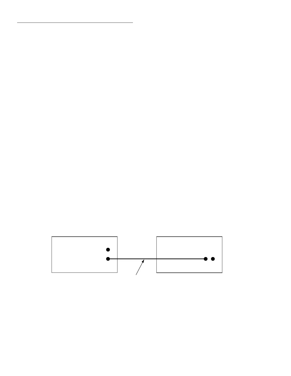
Semi-synchronous Trigger Link example
This example uses the same test system (Figure 3-29) that
was used for the Asynchronous Trigger Link example #1.
However, triggering is done using the Semi-synchronous
mode. Trigger Link connections are shown in Figure 3-38.
The two instruments are configured as follows:
Model 2001:
Idle state:
Bench reset = :INIT:CONT ON*
Arm layer:
Arm source = Immediate*
Arm count = 1*
Arm trigger control = Acceptor*
Scan layer:
Scan source = Immediate*
Scan count = Infinite*
Scan trigger control = Acceptor*
Measure layer:
Measure source = TrigLink
Trigger link mode = Semi-synchronous
Semi-sync line = #1*
Measure count = 10
Measure trigger control = Acceptor*
* Indicates that the setting is the BENCH RESET (and factory) default con-
dition.
Model 7001:
Idle state:
Reset = :INIT:CONT OFF*
Scan list = 1!1-1!10,
Arm layer:
Arm spacing = Immediate*
Arm count = 1*
Arm trigger control = Acceptor*
Scan layer:
Scan spacing = Immediate*
Number of scans = 1
Scan trigger control = Acceptor*
Channel layer:
Channel spacing = TrigLink
Trigger link mode = Semi-synchronous
Semi-sync line = #1
Number of channels = Use Scanlist length*
Channel trigger control = Source*
* Indicates that the setting is the RESET (and factory) default condition.
To run the test and store the readings in the Model 2001,
press STORE on the multimeter, enter the desired number of
readings (ten), and press ENTER. The Model 2001 waits
(with the asterisk annunciator lit) for a Trigger Link trigger
from the Model 7001. Press STEP on the Model 7001 to start
the scan.
The following explanation on operation is referenced to the
operation model shown in Figure 3-39.
igure 3-38
Trigger Link connections (semi-synchronous example)
Trigger
Link
7001 Switch System
Trigger Link
Cable
(8501)
IN
OUT
Line #1
Trigger
Link
2001 Multimeter
IN OUT