Front Panel Operation
3-32
FILTER
The FILTER parameter lets you set the digital filter response
and control its on/off operation. It is described in paragraph
3.9. Only the specifics for DC and AC current are covered
here.
The AUTO parameter for a digital filter optimizes its use for
the present measurement function. The defaults for automat-
ic filtering of DCI and ACI are listed in Table 3-14.
RESOLUTION
The RESOLUTION parameter sets the display resolution. It
is discussed in paragraph 3.4.1, DC and AC voltage. Only the
differences for DC and AC current are noted here.
The available resolution on all current functions and types is
3.5 digits to 7.5 digits. If the DCI or ACI resolution is AUTO,
refer to Table 3-15 for the resolution associated with the in-
tegration time.
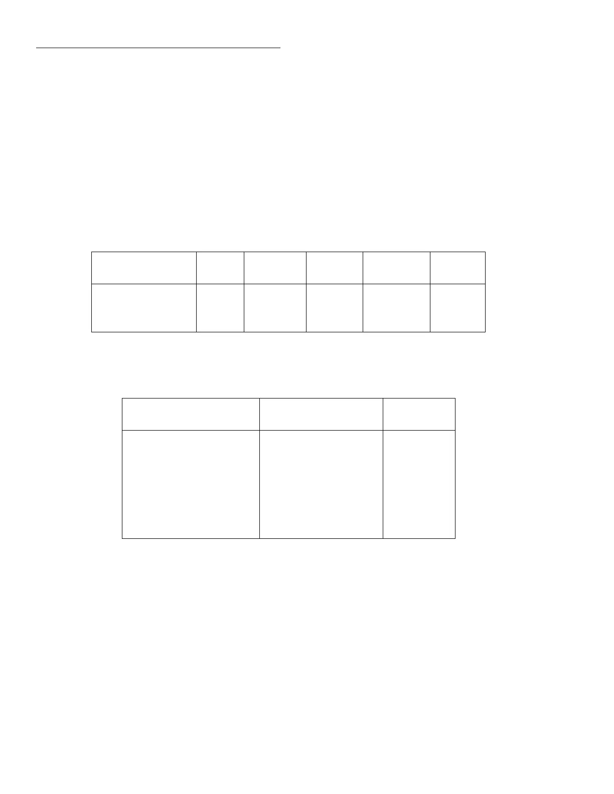
Table 3-14
DCI and ACI auto filter
Measurement function
and type State Type Readings
Noise
tolerance Mode
DC current On Advanced 10 1.0% Moving
DC in-circuit current On Advanced 10 1.0% Moving
AC current Off Advanced 10 5.0% Moving
Table 3-15
DCI and ACI auto resolution
Measurement function and
type Integration time Resolution
DC current 0.01 to <0.02 PLC
0.02 to <0.20 PLC
0.20 to <2.00 PLC
2.00 to 10.00 PLC
4.5d
5.5d
6.5d
7.5d
DC in-circuit current Not used 5.5d
RMS, average 0.01 to <0.02 PLC
0.02 to <10.00 PLC
10.00 PLC
4.5d
5.5d
6.5d
Notes:
1. For normal DC current, if the resolution is AUTO and the integration time is SET-BY-RSLN, the
resolution will be 6.5 digits and the integration time 1.0 PLC.
2. For DC in-circuit current, the integration time setting is ignored.
3. For AC current, if the resolution is AUTO and the integration time is SET-BY-RSLN, the resolution
will be 5.5 digits and the integration time 1.0 PLC.