Front Panel Operation
3-72
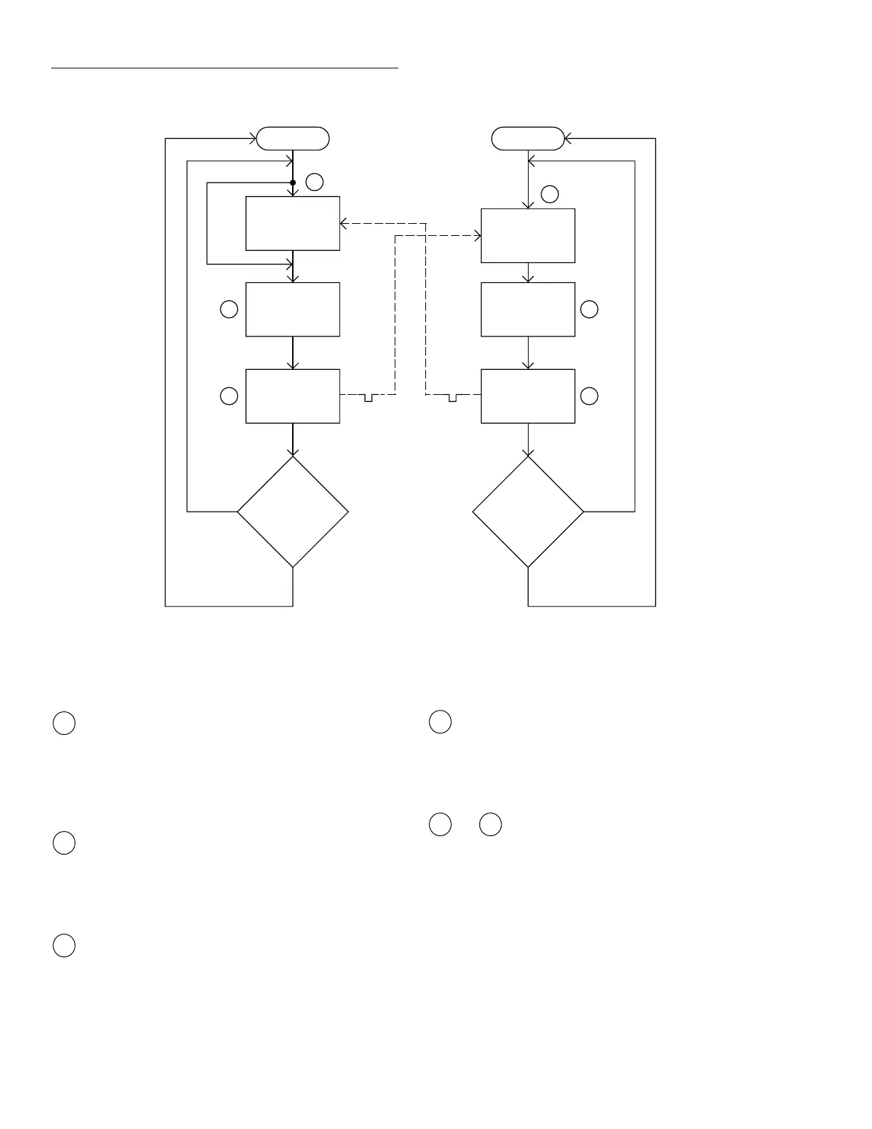
The BENCH RESET condition arms the Model 2001
and places multimeter operation at point A in the flow-
chart, where it is waiting for a Trigger Link trigger. Note
that since both the arm layer and scan layer are pro-
grammed for Immediate Source, operation immediately
drops down to the measure layer at point A.
Pressing STEP takes the Model 7001 out of the idle
state and places operation at point B in the flowchart.
Since both the arm layer and scan layer are programmed
for Immediate Spacing, operation drops down to the
channel layer at point B.
Since Channel Trigger Source is set to Source, the
scan does not wait at point B for a trigger. Instead, it by-
passes “Wait for Trigger Link Trigger” and closes the
first channel (point C). Note that the Bypass is in effect
only on the first pass through the model into a layer.
igure 3-31
Operation model for asynchronous trigger link example #1
Idle
Bypass
B
Wait for
Trigger Link
Trigger
Scan
Channel
C
Output
Trigger
Trigger
D
No
Scanned
10
Channels
?
Yes
7001
Make
Measurement
Made
10
Measurements
?
2001
Press STEP to start scan
Arm
A
Wait for
Trigger Link
Trigger
E
Output
Trigger
Trigger
F
No
Yes
A
B
C
After the relay settles, the Model 7001 outputs a Chan-
nel Ready pulse (point D). Since the instrument is pro-
grammed to scan ten channels, operation loops back up
to point B, where it waits for an input trigger. Note that
Bypass is no longer in effect.
and Remember that the Model 2001 operation is
at point A waiting for a trigger. The output Channel
Ready pulse from the Model 7001 triggers the multime-
ter to measure DUT #1 (point E). After the measurement
is complete, the Model 2001 outputs a completion pulse
(point F) and then loops back to point A, where it waits
for another input trigger.
The trigger applied to the Model 7001 from the Model 2001
closes the next channel in the scan. This triggers the multim-
eter to measure the next DUT. The process continues until all
ten channels are scanned and measured.
D
E F