Front Panel Operation
3-74
For this example, the Model 230 is programmed for External
Triggering and is set to source the first voltage level. The
Models 2001 and 7001 are configured as follows:
Model 2001:
Idle state:
Bench reset = :INIT:CONT ON*
Arm layer:
Arm source = Immediate*
Arm count = 1*
Arm trigger control = Acceptor*
Scan layer:
Scan source = Immediate*
Scan count = Infinite*
Scan trigger control = Acceptor*
Measure layer:
Measure source = TrigLink
Trigger link mode = Asynchronous
Input line = #3
Output line = #4
Measure count = 20
Measure trigger control = Acceptor*
* Indicates that the setting is the BENCH RESET (and factory) default
condition.
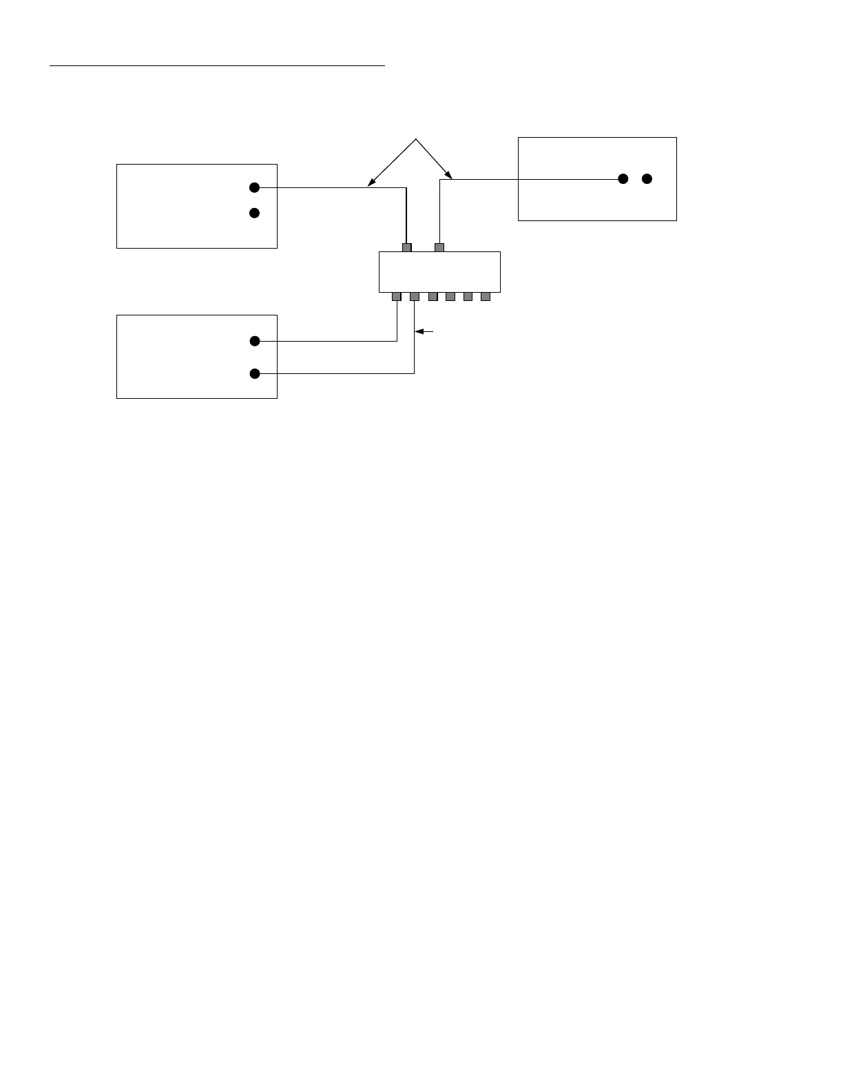
igure 3-34
Trigger Link connections (asynchronous example #2)
Trigger
Link
7001
Switch
System
Trigger
Link Cables
(8501)
IN
OUT
External Trigger
IN
OUT
230
Voltage
Source
8502
Trigger Link
Adapter
BNC to BNC
Cables
(7501)
1234
2001 Multimeter
Trigger
Link
IN OUT
56
Model 7001:
Idle state:
Reset = :INIT:CONT OFF*
Scan list = 1!1-1!10,
Arm layer:
Arm spacing = Immediate*
Arm count = 1*
Arm trigger control = Acceptor*
Scan layer:
Scan spacing = TrigLink
Trigger link mode = Asynchronous
Input line = #2
Output line = #1
Number of scans = 2
Scan trigger control = Source
Channel layer:
Channel spacing = TrigLink
Trigger link mode = Asynchronous
Input line = #4
Output line = #3
Number of channels = 20
Channel trigger control = Source*
* Indicates that the setting is the RESET (and factory) default condition.