Front Panel Operation
3-118
STROBE-CONTROL
This menu item enables or disables the use of digital output
#4 as a binning strobe signal.
If enabled, the strobe signal is set TRUE for greater than 10
microseconds after all limit tests have been performed on a
new reading. The FALSE to TRUE transition can be used to
trigger an external device handler to check digital outputs
#1-3 for sorting parts into bins.
When binning is enabled from the front panel or with the bus
command :CALCulate3:BSTRobe:STATe ON, the binning
strobe signal is set to FALSE. When binning is disabled, the
strobe signal is left unchanged.
To enable or disable strobe control, place the cursor on
STROBE-CONTROL and press ENTER. The following
menu is displayed:
LIMIT STROBE CONTROL
DISABLED ENABLED
Use the and keys to move the cursor to the desired
state, then press ENTER to select it and return you to the
LIMITS MENU.
PASS-PATTERN
This item allows you to program the on/off states of the dig-
ital output lines for when all limit tests pass. Note that when
the binning strobe is enabled, digital output line #4 cannot be
used.
To set a pass pattern, place the cursor on PASS-PATTERN
and press ENTER. The following menu is displayed:
PASS PATTERN
DIGOUT1=OFF 2=OFF 3=OFF 4=OFF
Use the and keys and the RANGE ▲ and ▼ keys to
move the cursor and toggle the parameter values between
OFF and ON. Pressing ENTER returns you to the LIMITS
MENU.
Limits example
This example sorts a quantity of 100Ω resistors into five bins,
according to the following tolerances:
• Values less than 90Ω (outside -10% tolerance).
• Values greater than 110Ω (outside +10% tolerance).
• Values between 90Ω and 99Ω (meets -10% tolerance).
• Values between 101Ω and 110Ω (meets +10% toler-
ance).
• Values between 99Ω and 101Ω (meets ±1% tolerance).
The desired test is shown in Figure 3-45. Use the following
procedure to program the limits:
1. From the LIMITS menu, set the limit values and actions
according to the following table:
2. Enable the binning strobe signal from the STROBE-
CONTROL item of the LIMITS menu.
3. Set a pass pattern of all lines off from the PASS PAT-
TERN item of the LIMITS menu.
4. Enable the control of the digital output lines by limit set
#1 and limit set #2 from the LIMIT SET #1 and LIMIT
SET #2 menus. This sets the digital output lines to the
“pass pattern” (all OFF in this example). Since binning
is enabled, digital output #4 is also OFF.
Note that the actual state (high or low) of the digital output
lines depends on the polarity (ACTIVE-HIGH or ACTIVE-
LOW). This is programmed from the DIGITAL I/O selection
of the GENERAL menu.
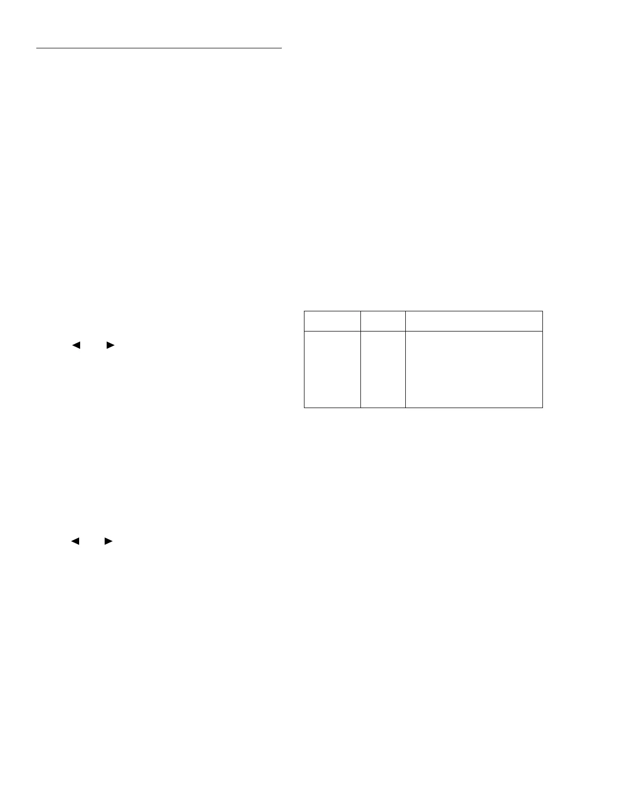
Table 3-44
Limit values and actions
Limit Value Action
LOLIM1 90Ω DIGOUT1=ON, others OFF
HILIM1 110Ω DIGOUT2=ON, others OFF
LOLIM2 99Ω DIGOUT1=ON, DIGOUT2=
ON, others OFF
HILIM2 101Ω DIGOUT3=ON, others OFF