Front Panel Operation
3-17
You can program the integration time parameter as follows:
1. From the normal reading display, press the CONFIG
key and then the appropriate function key to access the
top level of a function configuration menu. For example,
the CONFIGURE DCV menu is displayed as follows:
CONFIGURE DCV
SPEED FILTER RESOLUTION
2. Use the cursor keys ( and ) to highlight SPEED
and press ENTER. The following typical menu is
shown:
DCV MEASUREMENT SPEED
NORMAL FAST MEDIUM HIACCURACY
SET-SPEED-EXACTLY SET-BY-RSLN
3. Highlight the desired integration time and press EN-
TER. For all functions (except frequency), the parame-
ters are as follows:
NORMAL = 1 PLC
FAST = 0.01 PLC
MEDIUM = 0.1 PLC
HIACCURACY = 10 PLC
There are two additional parameters, SET-SPEED-
EXACTLY and SET-BY-RSLN. If the SET-SPEED-
EXACTLY parameter is chosen, the following message is
displayed:
NPLC=01.00 (.01-10)
By using the cursor keys ( and ) and the RANGE ▲
and ▼ keys, you can enter the integration time expressed in
power line cycles. Note that integer integrations time will in-
crease noise rejection.
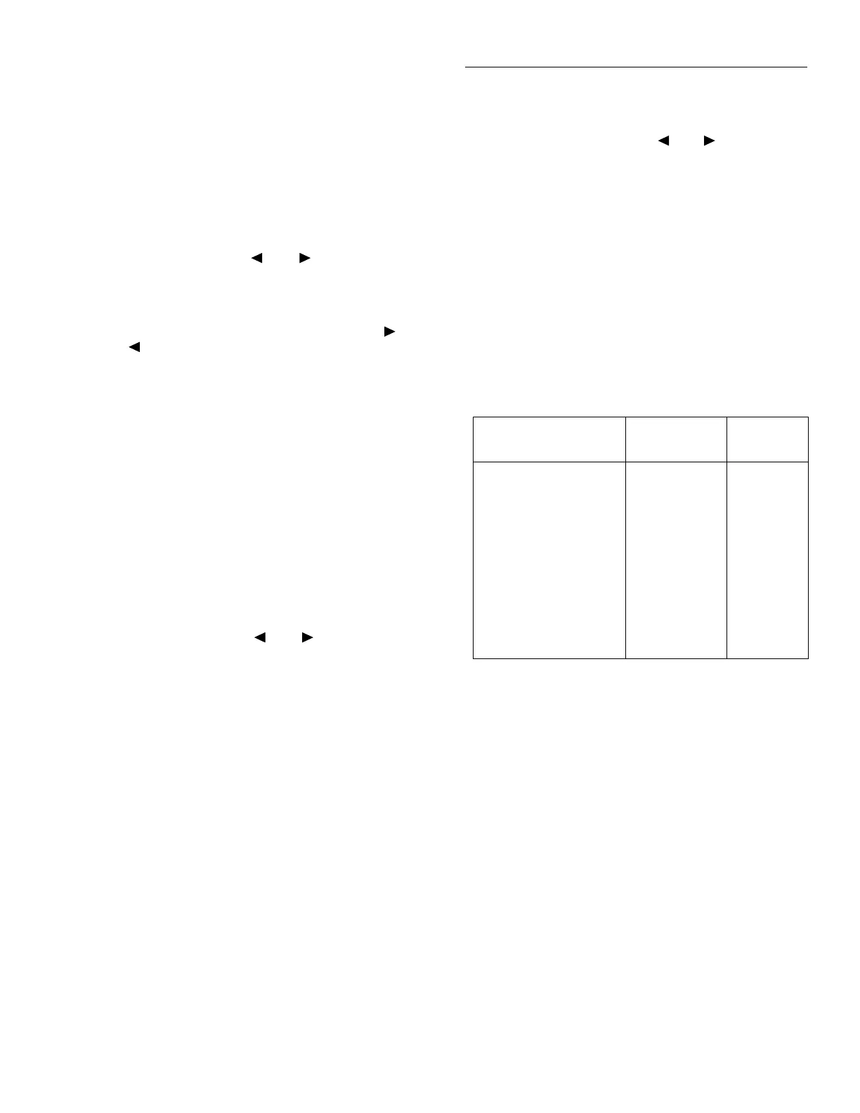
The SET-BY-RSLN parameter optimizes the integration
time for the present resolution setting. See Table 3-8 for the
default integration times of the DCV and ACV functions.
The default set-by-resolution integration times of other func-
tions are listed in paragraphs 3.4.2, 3.4.3, and 3.4.5.
ANALOG FILTER
The ANALOG-FILTER menu item is used to check and/or
change the state of the analog filter for the DCV function. It
is described in paragraph 3.9.
After selecting this menu item, cursor position indicates the
present state (ON or OFF) of the analog filter. To change the
state, place the cursor (using the and keys) on the al-
ternate selection and press ENTER.
FILTER
The FILTER parameter lets you set the digital filter response
and control its on/off operation. It is described in paragraph
3.9. Only the specifics for DC and AC voltage are covered
here.
The AUTO parameter for a digital filter optimizes its use for
the present measurement function. The defaults for automat-
ic filtering of DCV and ACV are listed in Table 3-9.
Table 3-8
DCV and ACV integration times set-by-resolution
Measurement function
and type Resolution
Integration
time
DCV 3.5d, 4.5d
5.5d
6.5d
7.5d
0.01 PLC
0.02 PLC
0.20 PLC
2.00 PLC
DCV peak spikes 3.5d (to 7.5d) Not used
RMS, average 3.5d, 4.5d
5.5d
6.5d, 7.5d
0.01 PLC
0.02 PLC
10.00 PLC
Low frequency RMS 3.5d to 7.5d Not used
ACV peak 4d (to 8d) Not used
Notes:
1. For DCV measurements, if the integration time is SET-BY-RSLN and
the resolution AUTO, the integration time will be 1.0 PLC and the
resolution 6.5 digits.
2. For RMS and average measurements, if the integration time is SET-
BY-RSLN and the resolution is AUTO, the integration will be 1.0
PLC and the resolution 5.5 digits.
3. For DCV peak spikes, low frequency RMS, and ACV peak measure-
ments, the integration time setting is ignored.
4. The resolution of DCV peak spikes can be from 3.5d to 7.5d, but the
accuracy is specified at 3.5d. The resolution of ACV peak can be from
4d to 8d, but the accuracy is specified at 4d.