Front Panel Operation
3-21
Note that dB and dBm are not allowed as valid units for peak
spikes. Positive-going spikes on a negative DC level could
still read as a negative value, and the log of a negative num-
ber is not defined.
Multiple displays
The displays for DC and AC voltage that show multiple func-
tions are shown in Figures 3-9 and 3-10. The multiple dis-
play for crest factor, which is calculated from the peak and
RMS values, is described here.
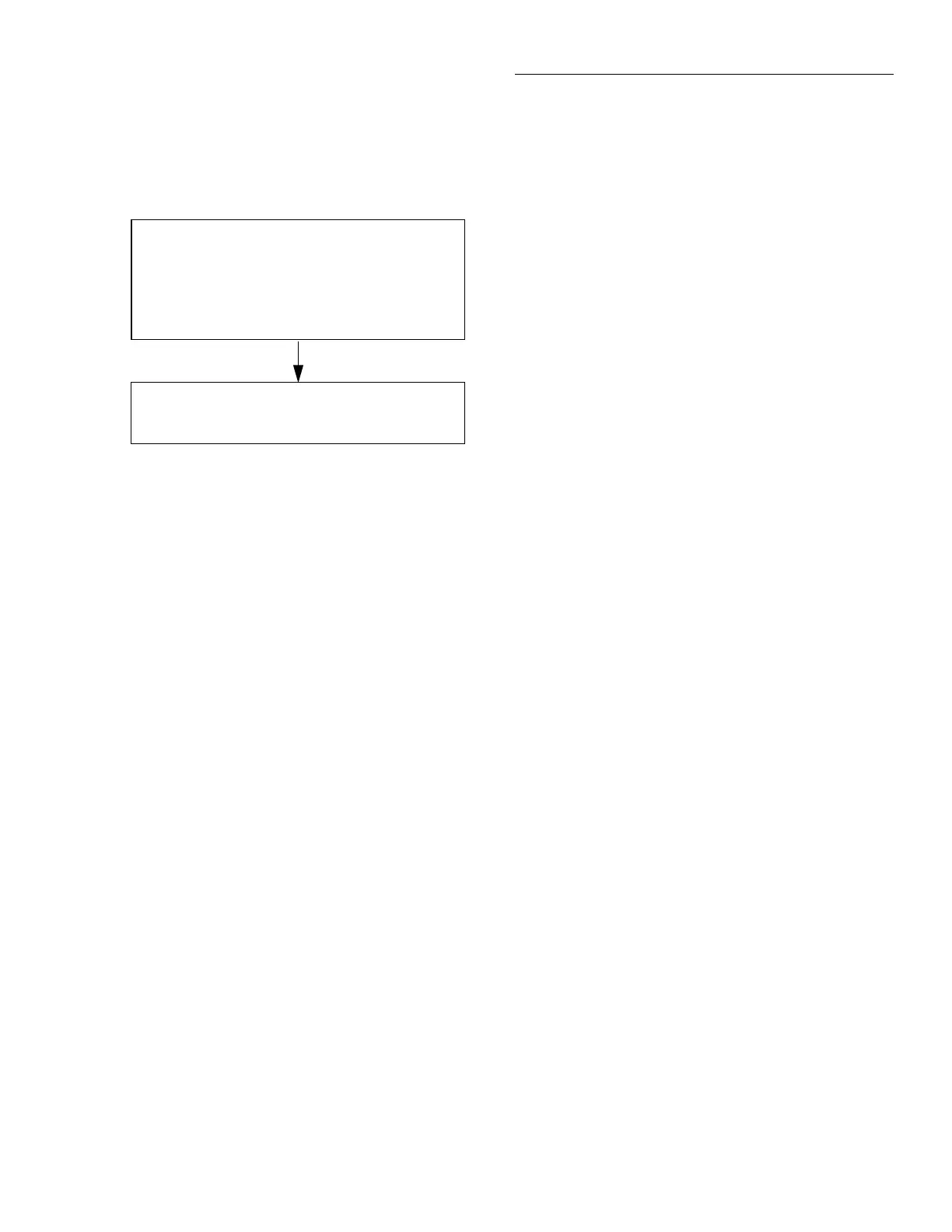
Figure 3-8
Positive and negative peak spikes
RANGE = Set by ACV range (auto or fixed).
REL = Operates normally.
SPEED = Set by peak window (0.1-9.9sec)
FILTER = Set by ACV filter (AUTO=ADV (10)).
RESOLUTION = Set by ACV resolution (AUTO = 3.5d)
UNITS = Fixed on volts.
COUPLING = Set by ACV coupling.
+000.0 mVAC +Pk
Coupling: AC+DC
NOTES:
1. Positive peak spikes and negative peak spikes are selected
in the CONFIGURE-ACV menu.
2. Peak spikes measurement is specified for volts at 3.5 digits.
3. “Peak window” is the time a signal is sampled before a
reading is displayed.