Front Panel Operation
3-121
An externally powered relay connected to the digital output
port is shown in Figure 3-48. Other externally powered
devices can be similarly connected by replacing the relay
with the device. When using the Model 2001’s collector
outputs to turn on externally powered devices, set the
corresponding digital output line parameters as follows
(through the GENERAL/DIGITAL I/O menus):
OUTPUT-STATE=ON
OUTPUT-SENSE=ACTIVE-LOW
In the low state (0V), the output transistor sinks current
through the external device. In the high state, the output
transistor is off (transistor switch is open). This interrupts
current flow through the external device. Most applications
use active-low (ON=0V) OUTPUT-SENSE. Use the
OUTPUT-SENSE menu to check or change the sense of the
digital output line.
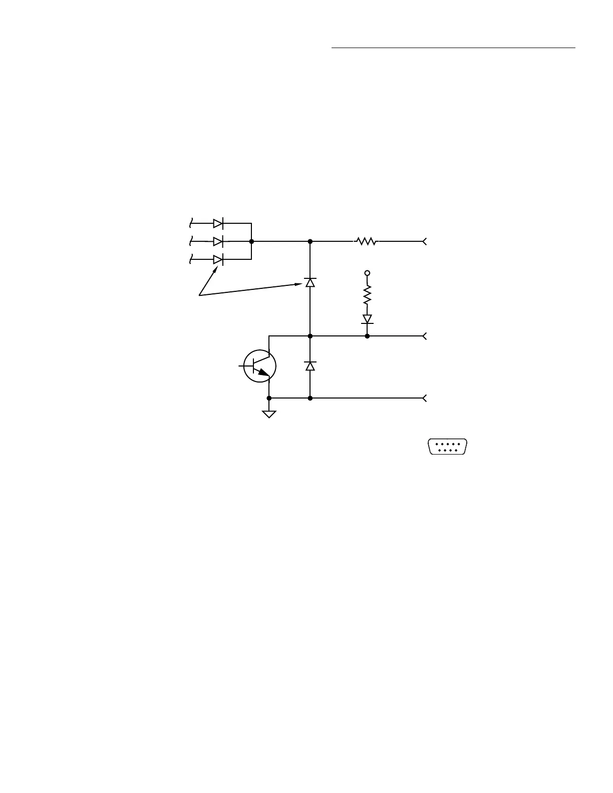
Figure 3-47
Digital I/O port simplified schematic
Pin 7 - Digital Output #2
+5V
10Ω
Digital Output
Flyback Diodes
10kΩ
Pin 8 - Digital Output #4
Pin 9 - Digital Output #3
Digital I/O Receptacle
51
96
(Connector J1031)
Pin 4 - External Voltage Flyback
connection (+5V to +30V)
Pin 6 - Digital Output #1
Pin 7 - Digital Output #2
Pin 8 - Digital Output #4
Pin 9 - Digital Output #3
Pin 5 - Digital Ground