Keysight B1505A Configuration and Connection Guide 2-21
N1259A Connection Guide
Output Connection
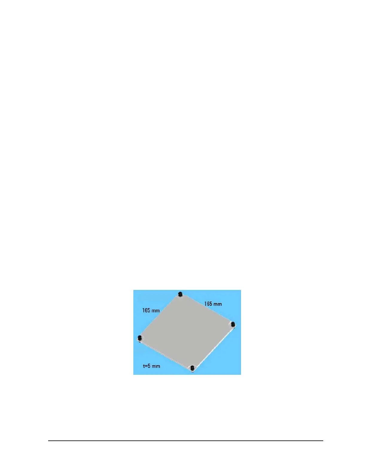
N1259A-012 Blank PTFE Board
This is an insulation board used for placing a DUT.
To use this board, see the following simple instruction.
• Required parts:
N1254A-508 or N1254A-509 connection wire, 1 ea. for one connection
N1254A-510 dolphin clip adapter or N1254A-511 cable lug adapter, 1 ea. for one
connection. Select one suitable for your DUT. See Table 2-5.
• Instruction:
1. Attach the blank PTFE board to the test fixture.
2. Connect adapters directly to the DUT and put it on the blank PTFE board.
3. Connect wires between the adapters and the fixture output terminals.
For making the Kelvin connection, Force and Sense must be connected together at
the device terminal.
If MCSMU, HCSMU, or DHCSMU is used, High Force and Sense must be
connected to the high terminal of a device under test (DUT). Low Force, Low
Sense, GNDU Force, and GNDU Sense must be connected to the low terminal of
the DUT. See Figure 2-3 for reference.
4. Make sure the DUT location. The DUT must be placed on the blank PTFE board
properly.
Make enough space between the adapters, also between the adapter of high side and
the shield/chassis, for example, about 1 mm for maximum 200 V output and 6 mm
for 3000 V, to prevent discharge and any accident.
5. Close the fixture cover and perform measurement.
Figure 2-12 Blank PTFE Board

 Loading...


