7-40 Keysight B1505A Configuration and Connection Guide
Connection and Ordering Examples
Configuration Examples for Lateral Device Measurement with Wafer Prober
3 kV, 500 A, Capacitance Measurement for On-Wafer
Lateral Device
• Device Type: Lateral MOSFET (4 terminals)
• Key Specification
• Max voltage/current: 3 kV/500 A
• Capacitance measurement up to 3 kV DC bias
• Module Selector for multi-parameter automated measurement function
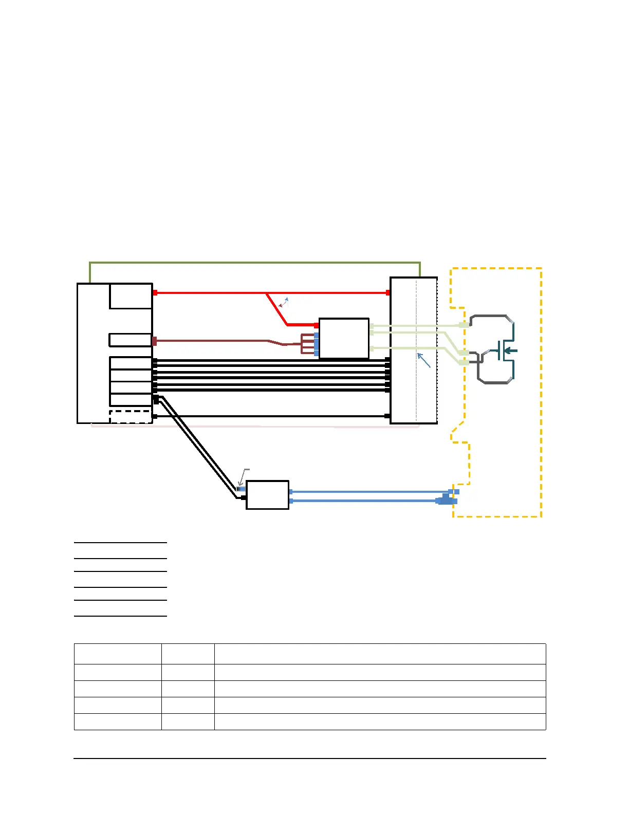
Figure 7-21 Connection example for CV measurement
NOTE The connection diagram in Figure 7-16 shows Cds measurement.
NOTE For IV measurement connection diagram, please refer to Figure 7-20.
NOTE Prober vendor is responsible for cabling inside the shielding box.
Table 7-19 Ordering example
Model/Option Quantity Description
B1505A 1 Power Device Analyzer/Curve Tracer mainframe
B1513C-FG 1 High Voltage Source Monitor Unit, 3000 V/4 mA (Pulsed & DC)
B1514A-FG 4 Medium Current Source Monitor Unit, 1 A/30 V(Pulsed), 100 mA/30 V(DC)
B1520A-FG 1 Multi Frequency Capacitance Measurement Unit Module
16494J I nterlock (Included in B1505A)
16493G-001 Digital I/O cable (Included in N1265A)
D
G
S
HVSMU
GNDU
MCSMU
B1505A
MCSMU
MCSMU
F
S
F
S
F
S
HVSM U
GND U
Gate F
Gate S
UHC Input
V Control
I Control
For Gate
For UHC
For UH C
For Drain
N1265A
MCSMU
F
S
Chuck
For Chuck
N1260A
Bias-T
To change connecƟon
manually
Hc
Hp
Lc
Lp
HV-F AC-H
AC-L
AC-Guard
MFCMU
N1300A (Included in the MFCMU)
N1254A-518
16494T (Included in the HVSMU)
16494T (Included in the HVSMU)
16493L (Included in B1505A)
16494A
(Included in the MCSMU)
HCSMU N on-
Kelvin adapter
16493S-011
N1254A-104 TRX(J) to BNC(P) adapter
16493U-001
16493U-001

 Loading...


