Keysight B1505A Configuration and Connection Guide 2-3
N1259A Connection Guide
Input Connection
Input Connection
Prepare the required cables listed in the following tables and connect them between the
B1505A terminals and the relative N1259A terminals. Table 2-1 shows the connections
without module selector, fast switch, and HVMCU.
Table 2-2 shows the additional connections for using module selector (N1259A-300).
Table 2-3 shows the additional connections for using HVSMU/HCSMU fast switch
(N1267A). For the additional information on the fast switch, see "To Connect
HVSMU/HCSMU Fast Switch" on page 5-32.
Table 2-4 shows the additional connections for using HVMCU. For the additional
information on the HVMCU, see "To Connect HVSMU Current Expander" on page 5-34.
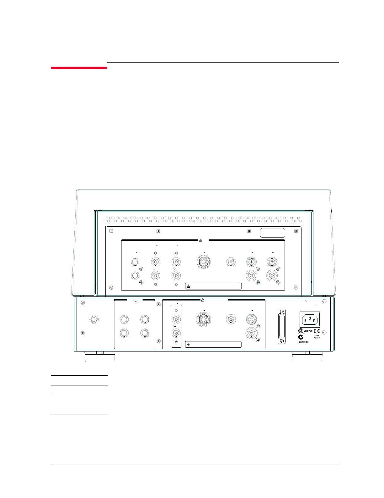
Figure 2-1 N1259A Rear View
WARNING The connector cap must be connected to the unused input connectors.
NOTE For connecting HP/MPSMU, use either 16494A or 16493K.
For connecting MFCMU, use either AUX or MFCMU only for N1259A-020.
N10149
Interlock
HPSMU3
±200 V Max
HVSMU2
±3 kV Max
GNDU2
Module Selector Input
Force
Sense
HVSMU1
±3 kV Max
GNDU1
Force
Sense
Force
Sense
Force
Sense
Force
Sense
Force
Sense
±25 V Max
HpotHcur
Lpot
Lcur
Digital I/O
LINE
100–240 V
50/60 Hz
35 VA Max
MF CMU Input
Input
To avoid electrical shock and instrument damage,
do not remove the short cap and cables during operation.
To avoid electrical shock and instrument damage,
do not remove the short cap and cables during operation.
HPSMU1
±200 V Max
HPSMU2
±200 V Max
HCSMU1
±40 V Max
AUX
±200 V Max
HCSMU2
±40 V Max
HCSMU3
±40 V Max
1
2
 Loading...


