Keysight B1505A Configuration and Connection Guide 5-49
Connection Guide for Wafer Prober and Your Own Test Fixture
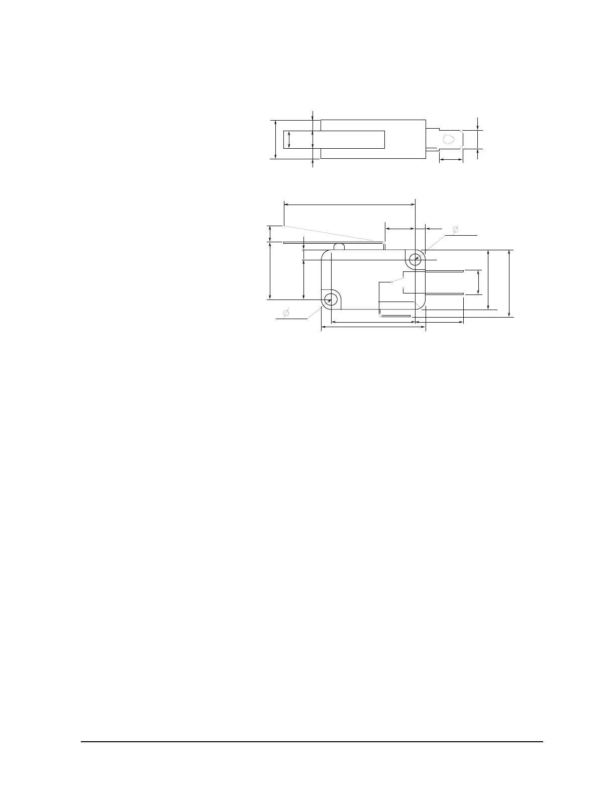
To Install an Interlock Circuit
Figure 5-27 Dimensions of the Interlock Switch (Keysight N1254A-402)
To Connect Interlock Circuit
The B1505A provides the Interlock connector to prevent you from receiving an electrical
shock from high voltage (more than ± 42 V). If the interlock circuit is open, the B1505A
cannot apply high voltage more than ± 42 V.
Before performing measurement, connect the 16493J interlock cable between the B1505A
Interlock connector and the interlock connector which is a part of the interlock circuit
installed in your DUT interface as described in "Procedure" on page 5-48.
3.1
35.6
8.1
14
NC
NO
COM
6.4
22.2
27.8
2.8
6.3 15.9 18.8
4.7510.3 4.3
2.8
2.8
3.2
10.3
2.8
3.1
Switch off
Units: mm
15.3

 Loading...


