4-14 Keysight B1505A Configuration and Connection Guide
N1272A and N1273A Connection Guide
Output Connection
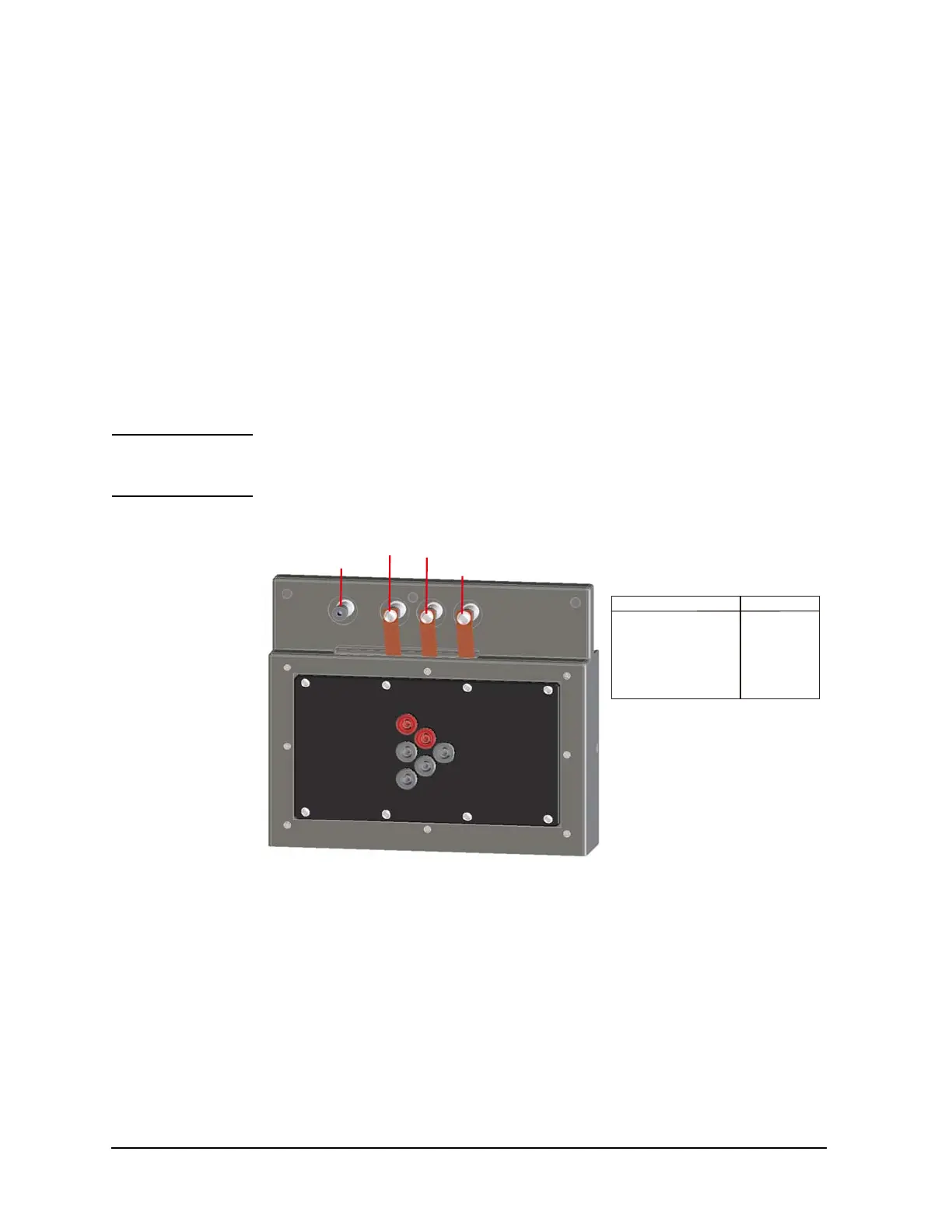
N1273A-013 Curve Tracer Test Adapter Socket Module
This module provides a socket available for connecting a test adapter designed for
connecting to Tektronix 370B/371B curve tracers. The socket module internal connection
is shown in Figure 4-9.
To use this module, see the following simple instruction.
• Instruction:
1. Attach the socket module to the test fixture.
2. Connect your test adapter to the socket.
Socket terminal: 4mm pin receptacle
3. Set the DUT on your test adapter.
4. Close the fixture cover and perform measurement.
CAUTION Do not apply voltage/current over the maximum limit of the socket module.
Maximum voltage: 3000 V
Maximum current: 100 mA
Figure 4-9 Curve Tracer Test Adapter Socket Module
1
2
3
4
5
6
Base / Gate
Collector / Drain
Emitter / Source
AC/DC Guard
Internal connections
Socket Terminal N1273A Output
1: Collector/Drain Force Collector/Drain
2: Collector/Drain Sense No Connection
3: Emitter/Source Force Emitter/Source
4: Emitter/Source Sense No Connection
5: Base/Gate Force Base/Gate
6: Base/Gate Sense No Connection

 Loading...


