Keysight B1505A Configuration and Connection Guide 3-25
N1265A Connection Guide
Output Connection
Figure 3-15 To Install Resistor in the N1265A-035 Universal R-Box, Connection for Case 1
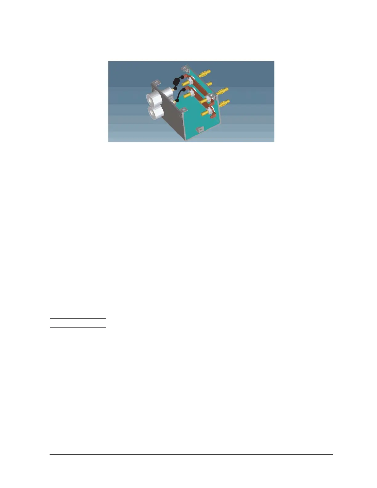
Protection Adapter (N1265A-040)
This is the adapter for protecting SMU from ultra high voltage.
If a SMU is used for the gate drive when performing the ultra high voltage measurement
using UHVU, this adapter must be connected to the SMU terminals for preventing SMU
from damage. See Figure 3-6 for connection example.
This adapter is designed for using the MCSMU.
Container (N1265A-045)
This container can accommodate protection adapters and bias-tee which are used with the
N1265A to make the measurement environment clean and safe.
Maximum superimposed load is 50 kg. The N1265A and the N1266A can be put on the top
of the container.
Prober System Cable (N1254A-524)
This is the cable for extending the N1265A’s Selector Output and Gate terminals to a
prober station. See "To Connect Ultra High Current Expander" on page 5-36 for more
information.
CAUTION Do not apply voltage/current over the maximum limit of the cable. See Table 5-28.
High Force
Low Force
High Sense
Low SenseHigh
Low

 Loading...


