7-44 Keysight B1505A Configuration and Connection Guide
Connection and Ordering Examples
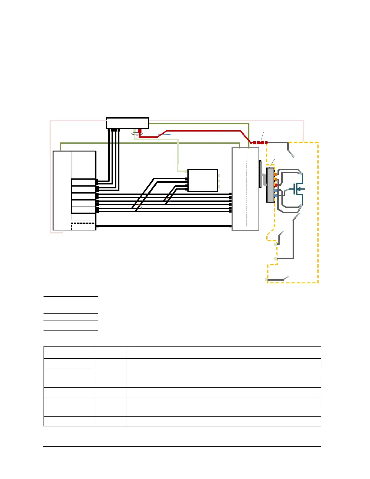
Configuration Examples for Lateral Device Measurement with Wafer Prober
10 kV, 500 A Measurement for On-Wafer Lateral Device
• Device Type: Lateral MOSFET (4 terminals)
• Key Specification
• Max voltage/current: 10 kV/500 A
Figure 7-23 Connection example
NOTE When using the N1268A, P1 to P4 terminals need to be connected to Gate, Source, Chuck
and Drain respectively, instead of the connection shown in Figure 7-23.
NOTE Prober vendor is responsible for cabling inside the shielding box.
Table 7-21 Required equipment, accessories, and cables
Model/Option Quantity Description
B1505A 1 Power Device Analyzer/Curve Tracer mainframe
B1514A-FG 5 Medium Current Source Monitor Unit, 1 A/30 V(Pulsed), 100 mA/30 V(DC)
16493V 1 10 kV Ultra High Voltage Cable
16493V-002 1 10 kV Ultra High Voltage Cable (3.0 m)
N1265A 1 Ultra High Current Expander/Fixture
N1265A-001 1 Ultra High Current Expander/Fixture
N1268A 1 Ultra High Voltage Expander
D
G
S
GNDU
MCSMU
B1505A
MC
MC
16493J Interlock cable
(Included in B1505A)
F
S
F
S
GNDU
UHC Input
V Control
I Control
For Gat e
HF
LF
HS
LS
G
ate
N1265A
Gate
Selector
Output
High
Low
N1254A-52 4
16493G-001 Digital I/O cable
(Included in N1265A)
MCSMU
MCSMU
N1268A UHV Exp
N1269A
P1
P2
P3
Gate
Source
Chuck
Chuck MCSMU F
Chuck MCSMU S
Gate MCSMU F
Gate MCSMU S
P3
To Chuck
P2
To S
P1
To G
MC
MC
F
S
F
S
MCSMU
MCSMU
F
S
For N1268 A
UHV Low
Chuck
For N1265 A
For N1265 A
/ Chuck
Gate F
Gate S
16493V-002 (3m cable)
16493G-001 Digital I/O control cable (Included in N1265A)
16493J-001 Interlock cable (Included in N1268A)
16494A (Included in the MCSMU)
16493L (Included in B1505A)
16494A (Included in the MCSMU)
N1254A-521
For N126 8A
F
S
F
S
F
S
F
S
To D
P4