Keysight B1505A Configuration and Connection Guide 5-47
Connection Guide for Wafer Prober and Your Own Test Fixture
To Install an Interlock Circuit
To Install an Interlock Circuit
The interlock circuit is designed to prevent electrical shock when a user touches the
measurement terminals.
You must install an interlock circuit on a shielding box to prevent hazardous voltages when
the door of the shielding box is open.
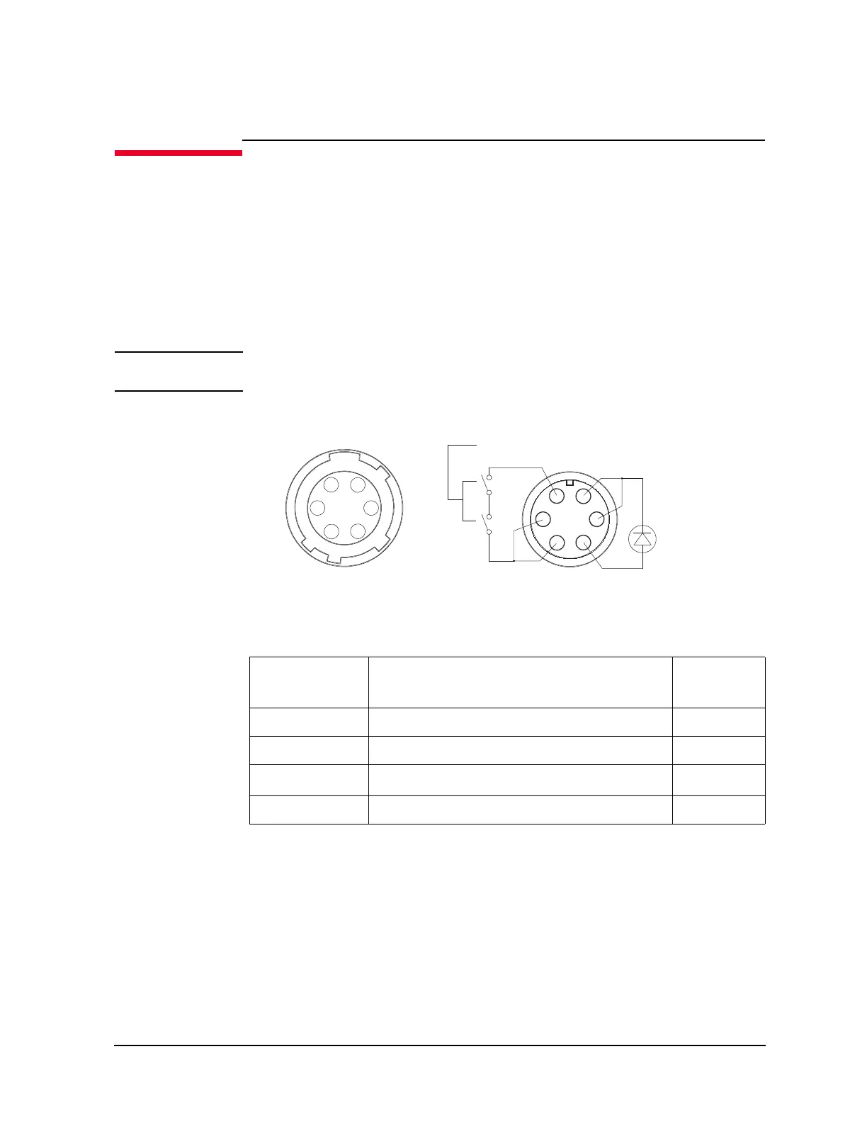
Figure 5-24 shows the pin assignments of the interlock connector that should be mounted
on your DUT interface. And Table 5-38 lists the required parts to make the interlock
circuit.
WARNING Potentially hazardous voltages may be present at the Force, Guard, and Sense
terminals when the interlock terminals are shorted.
Figure 5-24 Interlock Connector Pin Assignments
Table 5-38 Recommended Parts
Keysight Part
No.
Description Quantity
N1254A-402 Interlock micro switch 2
1252-1419 Interlock connector (6 pin, female) 1
1450-0641 LED (V
F
2.1 V @ I
F
= 10 mA) 1
Wire 24AWG, 600 V, 150 degree C or equivalent
1
2
34
5
6
Connector side
Interlock switch
Wiring side
LED
1
2
3
4
5
6

 Loading...


