5-48 Keysight B1505A Configuration and Connection Guide
Connection Guide for Wafer Prober and Your Own Test Fixture
To Install an Interlock Circuit
Procedure
Prepare the required parts listed in Table 5-38. And install the interlock circuit as shown
below.
1. Make mounting hole for the interlock connector. See Figure 5-26 for dimensions.
2. Mount two mechanical switches on your shielding box, so that the switches close when
the door of the shielding box is closed, and open when the door is opened. For the
dimensions of the switch, see Figure 5-27 below.
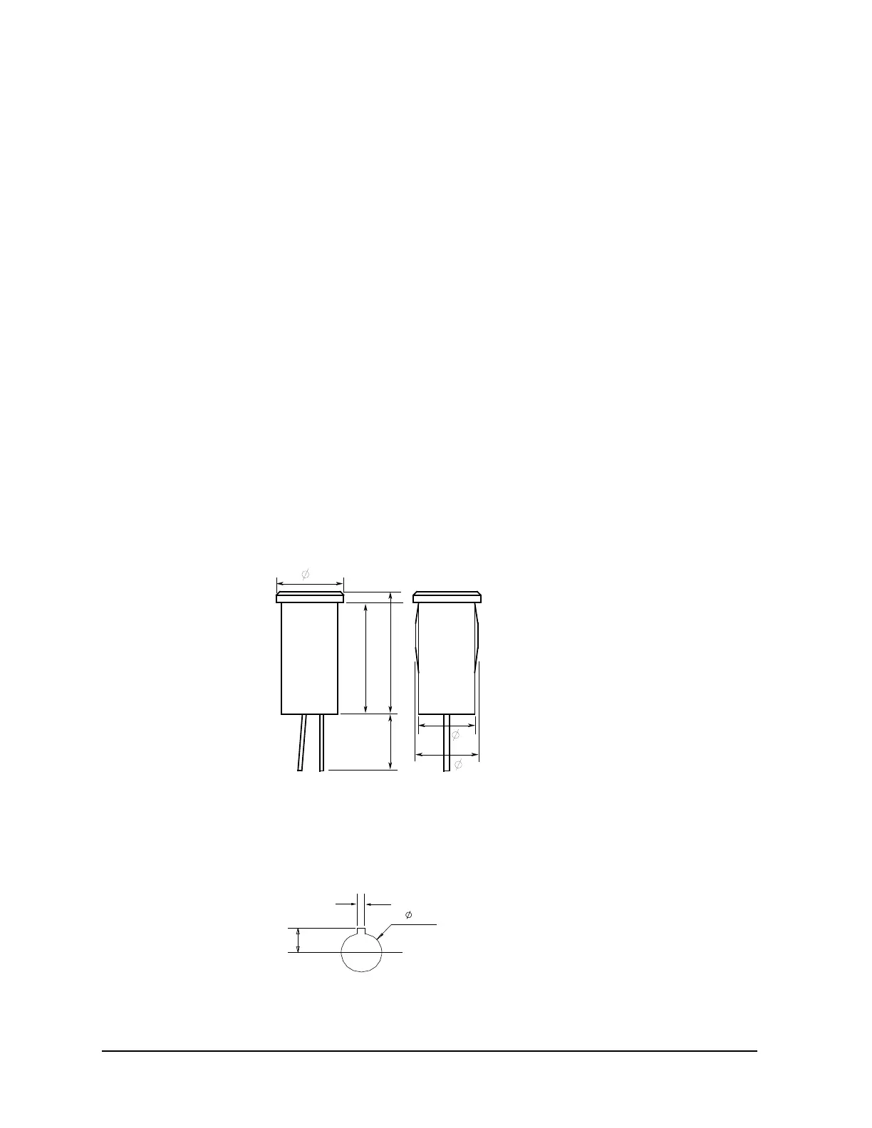
3. Mount an LED on your shielding box. For the dimensions of the LED, see Figure 5-25.
4. Use wire to connect the two switches in series between pin number 1 and 2 (or 3) of the
interlock connector. See Figure 5-24.
5. Use wire to connect the LED between pin number 4 and 5 (or 6) of the interlock
connector. See Figure 5-24.
6. Attach the interlock connector to the mounting hole.
If Keysight B1505A Interlock connector is connected to the interlock circuit, Keysight
B1505A SMU cannot force more than ± 42 V when the door is open. When the door is
closed, it can force more than ± 42 V.
When more than ± 42 V is forced from an SMU, the LED lights to indicate high voltage
output.
Figure 5-25 Dimensions of the LED (Keysight part number 1450-0641)
Figure 5-26 Dimensions of Mounting Hole for the Interlock Connector
6
10
11
5
5.6
5
Units: mm
Anode (+)
Cathode (-)

 Loading...


