Keysight B1505A Configuration and Connection Guide 3-19
N1265A Connection Guide
Output Connection
6. Mount the socket or DUT on the board and solder wire between its terminals and the
blank module terminals.
Make enough space between the socket/DUT terminal and the shield/chassis, for
example, about 1 mm for maximum 200 V output and 6 mm for 3000 V, to prevent
discharge and any accident.
7. Reattach the cover.
Curve Tracer Test Adapter Socket Module (N1265A-013)
This module provides a socket available for connecting a test adapter designed for
connecting to Tektronix 370B/371B curve tracers. Socket module internal connection is
shown in Figure 3-9.
CAUTION Do not apply voltage/current over the maximum limit of the socket module.
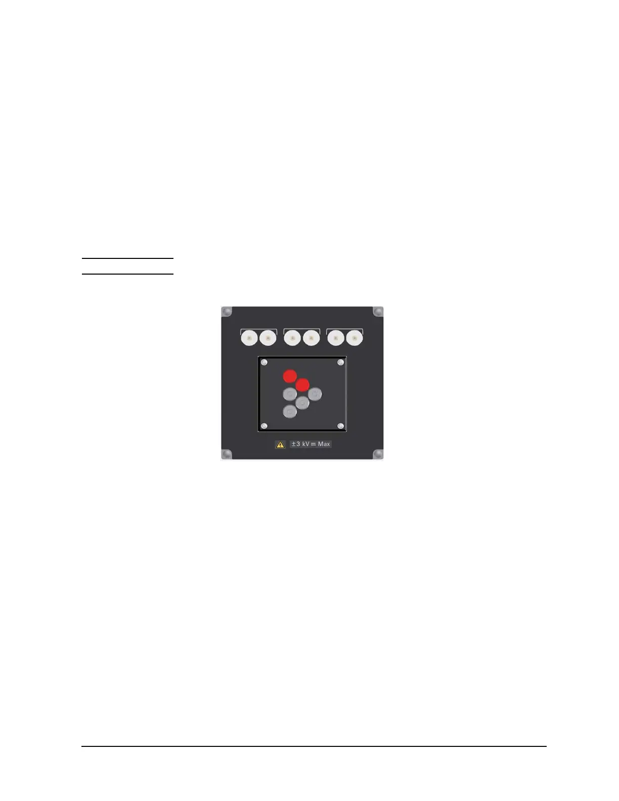
Figure 3-9 Curve Tracer Test Adapter Socket Module
To use this module, see the following simple instruction.
1. Attach the socket module to the test fixture.
2. Connect your test adapter to the socket.
3. Connect wires between the socket module terminals and the fixture output terminals.
Then use the following wire.
• N1254A-522 wire (yellow) for Selector Output High/Low Force
• N1254A-508 or 509 wire for Selector Output High/Low Sense, Gate, SMU, or
chassis
For making the Kelvin connection, Force and Sense must be connected to Force and
Sense of the socket module respectively.
For the high voltage capacitance measurement, use SHV(plug)-SHV(plug) cable
(N1254A-512) and SHV(jack)-banana adapter (N1254A-513) for connection.
Selector Output and Gate should be connected as follows.
• Selector Output High to DUT high (ex. Collector/Drain)
• Selector Output Low to DUT low (ex. Emitter/Source)
Collector / Drain
Emier / Source Base / Gate
N1265A Opt 013
Force Sense
Force Sense
Force Sense
Curve Tracer Test Adapter Socket
1
2
5
6
4
3
Internal connection
1: Collector/Drain Force
2: Collector/Drain Sense
3: Emitter/Source Force
4: Emitter/Source Sense
5: Base/Gate Force
6: Base/Gate Sense
Maximum voltage: 3000 V
Maximum current:
A-Force: 500 A pulse, 39 A dc
A-Sense: 40 A pulse, 2 A dc
B-Force: 500 A pulse, 39 A dc
B-Sense: 40 A pulse, 2 A dc
C-Force: 40 A pulse, 2 A dc
C-Sense: 40 A pulse, 2 A dc
A
BC

 Loading...


