7-76 Keysight B1505A Configuration and Connection Guide
Connection and Ordering Examples
Upgrading from existing B1505A
Example of how to upgrade existing B1505A
• Existing B1505A system configuration
• B1505A with one unit of B1512A HCSMU, one unit of B1513A HVSMU, two
units of B1510A HPSMU and one unit of B1520A MFCMU
• N1259A Test Fixture with N1259A-010 3-line inline socket module option,
N1259A-020 High Voltage Bias-Tee option and N1259A-300 Module Selector
option.
• Conditions and required specification
• Device Type: Three terminal discrete MOSFET
• Max voltage/current: 3 kV/1500 A
• Capacitance measurement up to 3 kV DC bias
• Drain leakage current measurement down to 10 fA
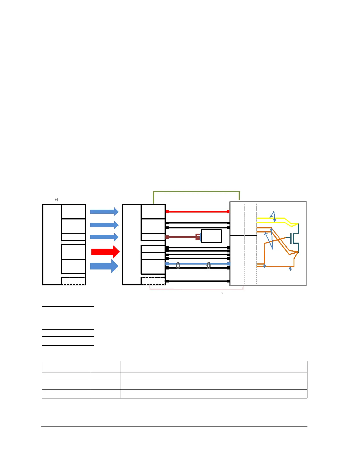
Figure 7-39 Connection example of upgraded B1505A
NOTE The N1259A-010 Inline Package Socket Module (3 pin) cannot be used with the N1265A
Ultra High Current Expander/Fixture due to its current limitation (maximum current is 40
A).
NOTE The N1259A-020 High Voltage Bias-Tee option cannot be re-used.
Table 7-36 Ordering example
Model/Option Quantity Description
B1505AU 1 Power Device Analyzer/Curve Tracer mainframe
B1505AU-014 2 Medium Current Source Monitor Unit (B1514A)
16494A 1 Triaxial Cable
Exis ng B1505A
HVSMU
GNDU
MFCMU
HPSMU
F
S
For Drain
For Drain
For Drain
For Gate
HPSMU
F
S
HCSMU
F
S
New B1505A
For Drain
For Drain
For Gate
F
S
F
S
N1265A
N1265A
Replaced with
2MCSMUs
Reused
Reused
Reused as a Gate
SMU
Reused
UHC Input
VControl
IControl
N1265A (Selector built-in)
GNDU
HVSMU
Gate F
Gate S
Gat e H
Gat e L
Forc e H
Forc e L
Sense H
Sense L
N1254A-522
(Included in N1265A-010)
N1254A-508
(Includ ed in N12 65A-010)
N1254A-509
(Included in N1265 A-010)
N1 26 5- 6 1 75 1 &
N1265A-612752
(Include d in N1265 A- 010)
Selector
Output
Selec tor
Input
16493J-001 Interlock cable (Included in exi ng B1505A)
16493G-001 Digital I/O cable (Included in N1265A)
16493T
16493L-001 (Included in B1505A)
16494A
HVSMU
GNDU
MFCMU
HPSMU
HCSMU
MCSMU
MCSMU
F
S
F
S
SMU H
SMU L
16494A
N1260A
Bias-Tee
F
S
F
S
N1300A
16493S

 Loading...


