Keysight B1505A Configuration and Connection Guide 5-53
Connection Guide for Wafer Prober and Your Own Test Fixture
About Cable Connections
• For the non-Kelvin connection, the voltmeter measures the voltage drop of resistances
r
F1
, R
DUT
, and r
F2
.
• For the Kelvin connection, the voltmeter measures the voltage drop of resistance R
DUT
only. The impedance of the voltmeter is very high, so the voltage drop of resistances
r
S1
and r
S2
can be ignored.
The Kelvin connection is effective even when forcing voltage. The voltage drop due to the
residual resistance of the Force line wiring is fed back to the voltage source via a
comparator in the Sense line. The input impedance of comparator is high, and current flow
into the Sense line is very low. So output error is not significant if the Sense line wiring has
a residual resistance of 10 or less. Therefore, the specified voltage appears at the sense
point (point where Sense line contacts Force line)
NOTE Kelvin connection and non-Kelvin connection
To make the Kelvin connection, use both Force and Sense terminals. Connecting the Force
and Sense lines together at the terminal of the DUT (device under test) minimizes the
measurement error caused by the residual resistance of the connection cables. The Kelvin
connection is effective for the low resistance measurement and the high current
measurement.
If you want to simplify the cable connections, open the Sense terminals and use the Force
terminals only. This is the non-Kelvin connection. The Force terminals can be used to force
and measure dc voltage or current.
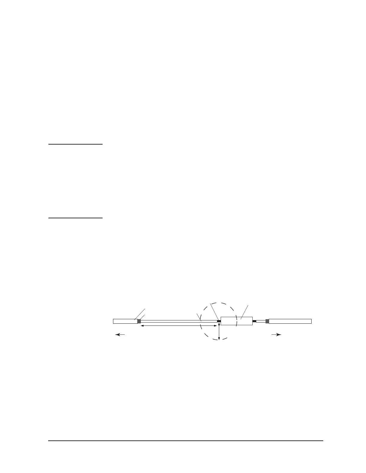
To Connect UHVU/HVSMU/HVMCU Output
To prevent discharge and any accident, make enough space between the cable ends, also
between the high side cable end and the shield or chassis. For example, make space of
about 32 mm from the high side cable end for maximum 10 kV output. Also the creepage
distance must be more than 100 mm for 10 kV.
Figure 5-28 Space around Cable End
To UHVU High
To UHVU Low
DUT
Shield
Signal line
Insulator
SHV CableUHV Cable
Insulator
¡32 mm for 10 kV
¡100 mm for 10 kV