7-2 Keysight B1505A Configuration and Connection Guide
Connection and Ordering Examples
This chapter describes prober connection and ordering examples of Keysight B1505A
Power Device Analyzer/Curve Tracer, and consists of the following sections.
• "Package Device Measurement Configuration Examples"
• "Configuration Examples for Lateral Device Measurement with Wafer Prober"
• "Configuration Examples for Vertical Device Measurement with Wafer Prober"
• "GaN Current Collapse / Dynamic On-Resistance Measurement System using the
N1267A"
• "Upgrading from existing B1505A"
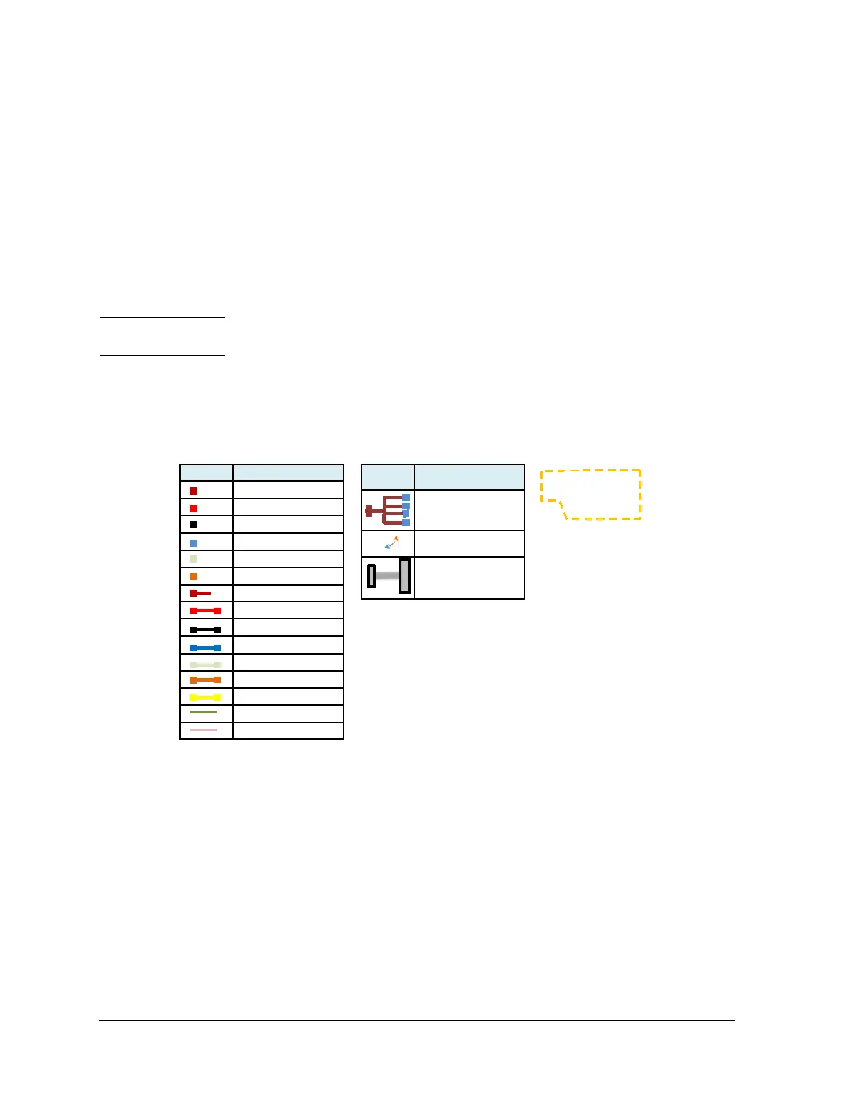
NOTE Please view connection diagrams included in this Chapter in color because cables and
connectors are color-coded according to their types.
Figure 7-1 Legend
Prober vender provides items
surrounded by the doƩed
yellow line.
Mark DescripƟon
UHV connector
HVTRX co nnecter
TRX conn ecter
BNC connecter
SHV connecter
Banana connector
UHV cable
HVTRX cable
TRX cable
BNC cabl e
SHV cable
Banana cable
1500 A UHC Banana cable
Digital I/O cable
Interlock cable
Mark DescripƟon
CMU Cable
To change connecƟon
ma nu ally
N1254A-524
500 A Ul tr a Hig h C urrent
Prober System Cable

 Loading...


