Keysight B1505A Configuration and Connection Guide 7-49
Connection and Ordering Examples
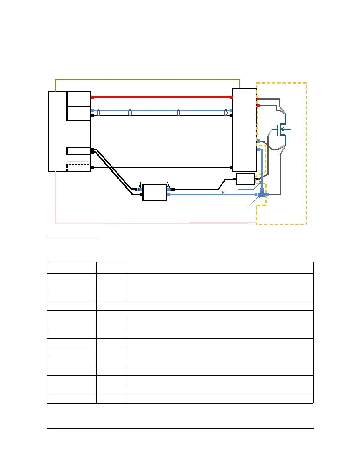
Configuration Examples for Vertical Device Measurement with Wafer Prober
Figure 7-25 Connection example for 3 kV/20 A automated measurement with N1258A Module
Selector
NOTE Prober vendor is responsible for cabling inside the shielding box.
Table 7-24 Required equipment, accessories, and cables
Model/Option Quantity Description
B1505A 1 Power Device Analyzer/Curve Tracer mainframe
B1512A-FG 1 High Current Source Monitor Unit, 20 A/20 V(Pulsed); 1 A/40 V(DC)
B1513C-FG 1 High Voltage Source Monitor Unit, 3000 V/4 mA (Pulsed & DC)
B1514A-FG 1 Medium Current Source Monitor Unit, 1 A/30 V(Pulsed), 100 mA/30 V(DC)
16493U 1 High Current BNC Coaxial Cable
16493U-001 2 High Current BNC Coaxial Cable (1.5 m)
16494A 1 Triaxial Cable
16494A-003 1 Triaxial Cable (80 cm)
1250-2405 1 BNC-T Plug (m)-BNC (f)-BNC (f) adapter, 1ea
N1258A 1 Module Selector for B1505A
16493S 1 High Current Source Monitor Unit Cable
16493S-011 1 High Current Source Monitor Unit non-Kelvin Adapter
N1262A 1 R-box for B1505A
N1262A-010 1 1 kohm R-box for gate (Triaxial output)
HVSMU
HCSMU
GNDU
MCSMU
B1505A
N1258A
G
S
HCSMU Non-
Kelvin adapter
16493S-011
For Gate
16493G-001 Digital I/O cable (Included in N1258A)
N1254A-104 TRX(J) to BNC(P) adapter
F
S
F
S
High F
High S
Low S
Low F
Digital I/O
HV SM U
HCSMU F
HCSMU S
GNDU
16493J-001 Interlock cable
D
(Chuck)
For Drain
For Drain
16493T (Included in the HVSMU)
16493S (Included in the HCSMU)
16494A (Included in the MCSMU)
16493L (Included in B1505A)
16493U-001
1250-2405
16494A-003
R-Box
1kO
N1262A-010

 Loading...


