454 N9030B PXA Signal Analyzer Service Guide
Assembly Replacement Procedures
RF Area (Options 503, 508, 513, 526)
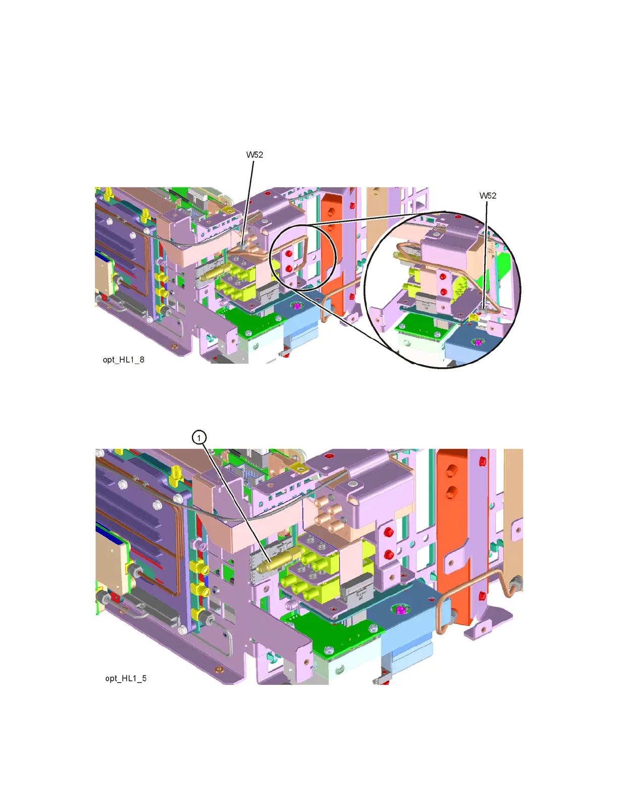
8. Refer to Figure 16-20. Remove cable W52 (N9020-20146) between top
switch port 4 and Low Band Switch Assembly connector that is closest to
the inner chassis.
Figure 16-20 W52 Cable Removal
9. Refer to Figure 16-21. Remove the coaxial fixed attenuator (1),
Figure 16-21 Attenuator Removal