N9030B PXA Signal Analyzer Service Guide 459
Assembly Replacement Procedures
RF Area (Options 503, 508, 513, 526)
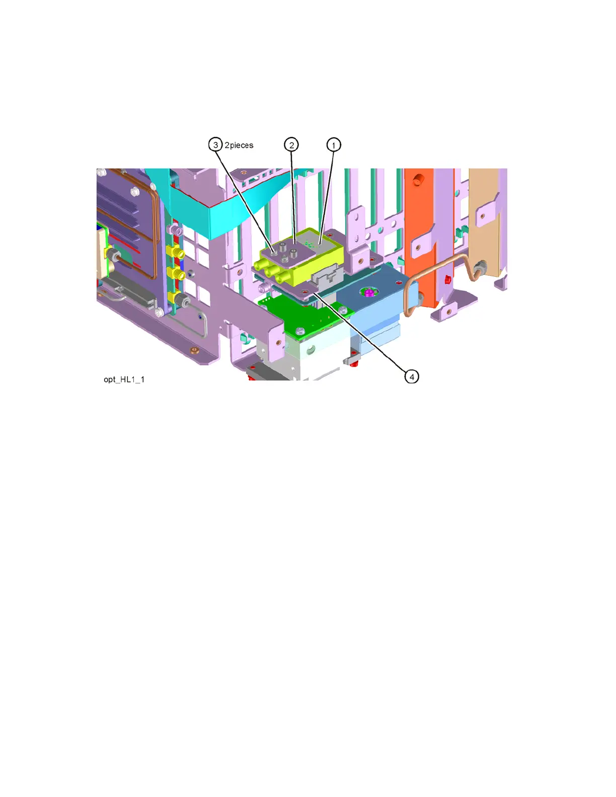
15.Refer to Figure 16-27. Remove the bottom switch/bracket assembly
(1)/(2) by removing the two screws on the top (3) (0515-1992).
Figure 16-27 Switch 1 Removal
Replacement
1. Refer to Figure 16-28. Place the switch/bracket assembly (1)/(2) on the
Low Band bracket (4) with the label facing up. Use the two screws (3 )
(0515-1992) to attach to the Low Band bracket. Do not torque screws at
this time.