486 N9030B PXA Signal Analyzer Service Guide
Assembly Replacement Procedures
RF Area (Options 544, 550)
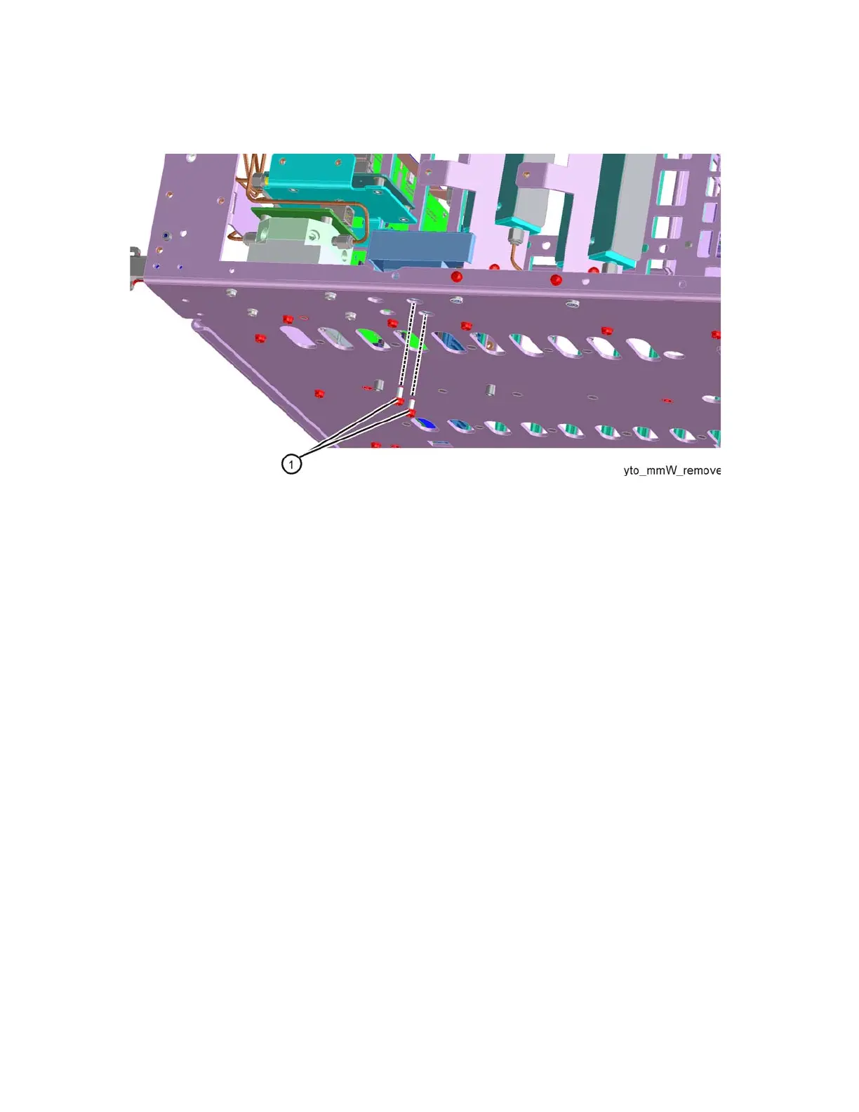
Figure 16-52 YTO Screws
Replacement
1. Refer to Figure 16-52. Place the YTO into the chassis. Replace the two
screws (1) (0515-0372). Torque to 9 inch-pounds.
2. Figure 16-51. Replace the cables W20. Torque to 10 inch-pounds.
3. Replace the ribbon cable W23. Ensure the locking latch is engaged.
4. Refer to Figure 16-43. Position the RF bracket onto the chassis and
replace the sixteen screws (0515-0372). Torque to 9 inch-pounds.
5. Replace the front panel. Refer to the Front Frame Assembly replacement
procedure.
6. Replace the instrument outer case. Refer to the Instrument Outer Case
replacement procedure.