488 N9030B PXA Signal Analyzer Service Guide
Assembly Replacement Procedures
RF Area (Options 544, 550)
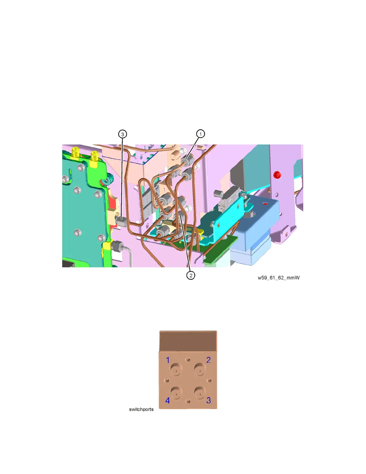
2. Refer to Figure 16-54 and Figure 16-55. Remove cable W62
(N9020-20130) (3) from bottom switch port 2 to Front End Assembly J9.
3. Remove cable W61 (N9020-20129) (2) from bottom switch port 3 to YTF
Assembly.
4. Remove cable W59 (N9020-20151) (1) from top switch port 2 to bottom
switch port 1.
Figure 16-54 W62, W61, and W59 Cables Removal
Figure 16-55 Switch Ports