492 N9030B PXA Signal Analyzer Service Guide
Assembly Replacement Procedures
RF Area (Options 544, 550)
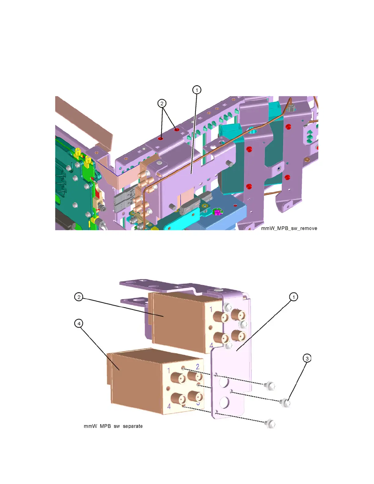
11.Refer to Figure 16-59. Remove the switch assembly (1) by removing the
two screws (0515-2032) at the frame (2).
Figure 16-59 Switch Assembly Removal
12.Refer to Figure 16-60. To separate the switches (2) and (4) from the
bracket (1 ) (N9020-00021), remove the three screws (3) (0515-1934) for
each switch.
Figure 16-60 Bracket Mount to Switches