l Cable resistance - Varies with wire gauge size and cable length. Use the largest gauge wire pos-
sible and try to keep the cable lengths as short as possible to minimize the cable resistance.
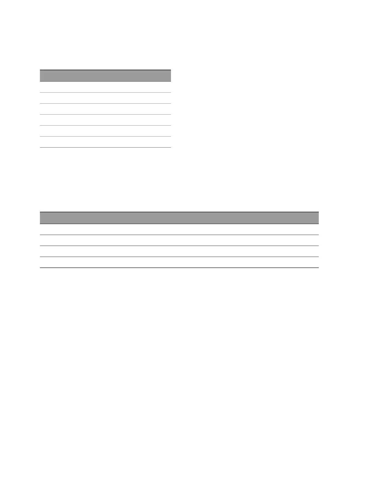
The following table lists typical cable resistance for copper wire of several gauge sizes (the tem-
perature coefficient for copper wire is 0.35% per °C).
AWG Ω / ft (2 conductors) at 25 °C
14 5 mΩ
16 10 mΩ
18 15 mΩ
20
[1]
20 mΩ
22 30 mΩ
24 50 mΩ
[1] Recommended wire size for the screw terminals on the DAQ970A plug-in modules.
l Cable capacitance - Varies with insulation type, cable length, and cable shielding. Cable
should be kept as short as possible to minimize cable capacitance. In some cases, low-capa-
citance cable can be used.
The table below lists the typical cable specifications.
Cable type Nominal impedance Capacitance Attenuation
Twisted pair 100 Ω at 1 MHz 10 to 20 pF/ft Up to 1 dB/100 ft at 1 MHz
Shielded twisted pair 100 Ω at 1 MHz 10 to 20 pF/ft Up to 1 dB/100 ft at 1 MHz
Coaxial 50 Ω or 75 Ω at 100 MHz 15 to 25 pF/ft Up to 6 dB/100 ft at 100 MHz
Twisted pair ribbon 100 Ω at 1 MHz 15 to 20 pF/ft Up to 1 dB/100 ft at 1 MHz
Keysight DAQ970A User's Guide 177
4Measurement Tutorials