Capacitance is calculated by measuring the change in voltage (DV) that occurs over a “short aperture” time,
(Dt). This measurement is repeated at two different times during the exponential rise that occurs. An
algorithm takes the data from these four points, and by linearizing that exponential rise over these “short
apertures”, accurately calculates the capacitance value.
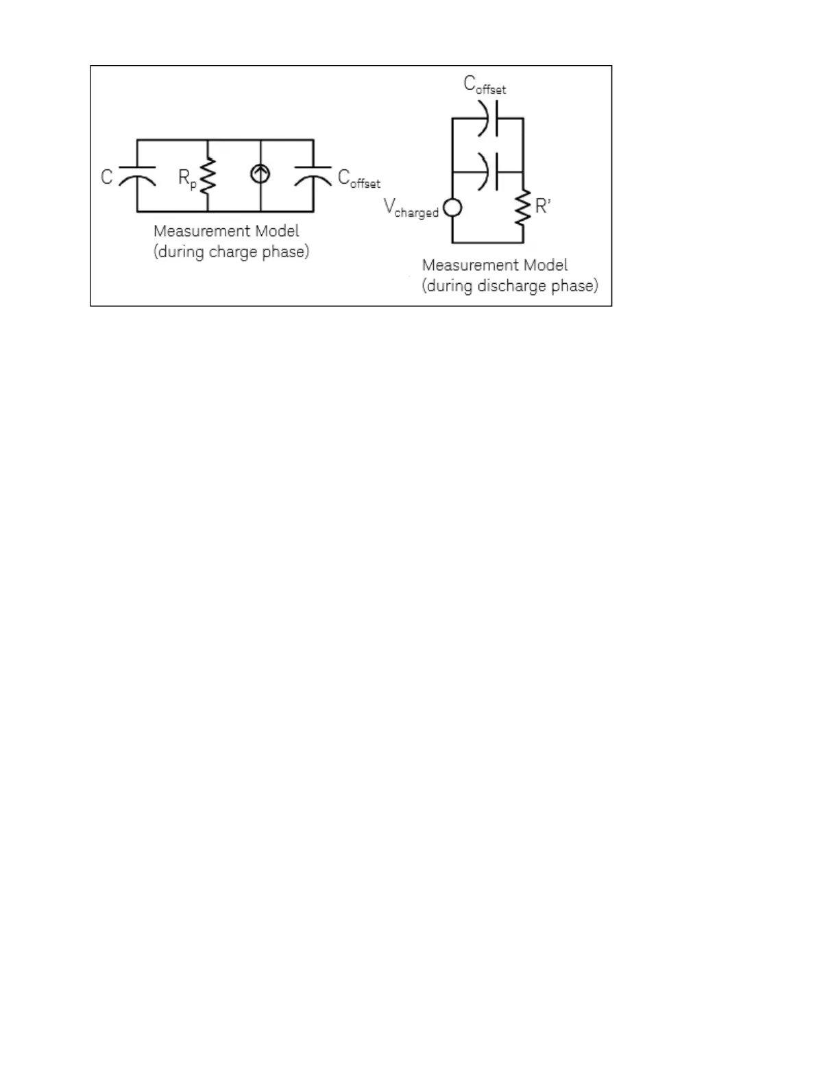
The measurement cycle consists of two parts: a charge phase (shown in the graph) and a discharge phase.
The time–constant during the discharge phase is longer, due to a 100 kΩ protective resistor in the meas-
urement path. This time–constant plays an important role in the resultant reading rate (measurement
time). The incremental times (or “sample times”) as well as the width of the “short apertures”, vary by range,
in order to minimize noise and increase reading accuracy. For the best accuracy, take a zero null meas-
urement with open probes, to null out the test lead capacitance, before connecting the probes across the
capacitor to be measured.
Capacitance Measurement Considerations
Capacitors that have a high dissipation factor or other non-ideal characteristics will affect capacitance
measurements. Capacitors with high dissipation factors may exhibit a variance between the measured value
using the multimeter versus the single frequency method of some other LCR meters. The single frequency
method will also see more variation at different frequencies. For example, some inexpensive capacitance
substitution boxes, when measured with the multimeter, are almost 5% different compared to the same
capacitance measured with the single frequency method of an LCR meter. The LCR meter will also show dif-
ferent values at different frequencies.
Capacitors with long time constants (dielectric absorption) will result in slow measurement settling time,
and will take a number of seconds to stabilize. You may see this when first connecting a capacitor or when
the delay time to make a measurement is varied. A high quality film capacitor typically shows the least of this
and an electrolytic capacitor the most, with ceramic capacitors typically in between.
Low-Level Signal Multiplexing and Switching
Low-level multiplexers are available in the following types: one-wire, 2-wire, and 4-wire. The following sec-
tions in this chapter describe each type of multiplexer. The following low-level multiplexer modules are
available with the DAQ970A.
DAQM900A 20-Channel FET Multiplexer
DAQM901A 20-Channel Armature Multiplexer
Keysight DAQ970A User's Guide 211
4Measurement Tutorials