where L is the inductance of the load and I
o
is the current value calculated earlier.
The total circuit capacitance (C) is actually made up of the wiring capacitance plus the value of the pro-
tection network capacitor (C
p
). Therefore, the minimum value for C
p
should be the value obtained for the
total circuit capacitance (C). Note that the actual value used for C
p
should be substantially greater than the
value calculated for C.
Using Varistors
Use a varistor to add an absolute voltage limit across the relay contacts. Varistors are available for a wide
range of voltage and clamp energy ratings. Once the circuit reaches the voltage rating of the varistor, the
varistor’s resistance declines rapidly. A varistor can supplement an RC network and is especially useful when
the required capacitance (C
p
) is too large.
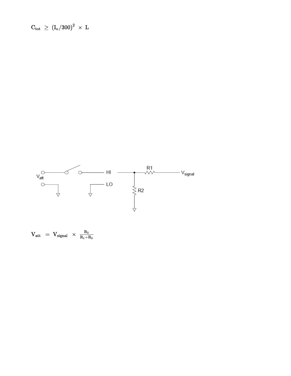
Using Attenuators
Provisions have been made on the DAQM903A circuit board for installing simple attenuators or filter net-
works. An attenuator is composed of two resistors that act as a voltage divider. A typical attenuator circuit
is shown below:
To select the attenuator components, use the following equation:
One typical use for the shunt component is with 4 to 20 mA transducers. A 50 Ω, ±1%, 0.5 watt resistor can
be installed in the R2 location. The resultant voltage drop (transducer current through the resistor) can be
measured by the internal DMM. Thus, the 50 Ω resistor converts the 4 to 20 mA current to a 0.2 to 1 volt
signal.
Matrix Switching
A matrix switch connects multiple inputs to multiple outputs and therefore offers more switching flexibility
than a multiplexer. Use a matrix for switching low-frequency (less than 10 MHz) signals only. A matrix is
arranged in rows and columns. For example, a simple 3x3 matrix could be used to connect three sources to
three test points as shown below:
4Measurement Tutorials
218 Keysight DAQ970A User's Guide