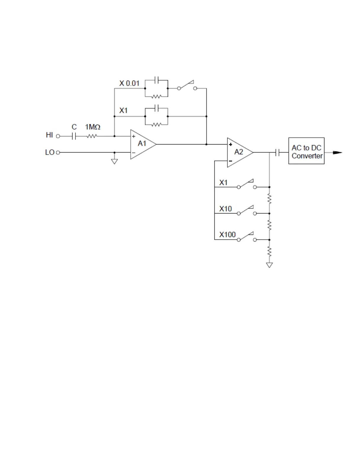
Input signal conditioning for AC voltage measurements includes both attenuation and amplification. An
input coupling capacitor (C) blocks the DC portion of the input signal so that only the AC component is
measured. Ranging is accomplished by combining signal attenuation from the first-stage amplifier and
gain from the second-stage amplifier.
The first stage implements a high input impedance (1 MΩ) switchable compensated attenuator. The
second stage provides variable-gain signal amplification to scale the input to the AC converter to the full-
scale level. Any residual DC offset from the attenuator and amplifier stages is blocked by a capacitor.
An AC voltage front end similar to the one discussed above is also used to measure AC current. Shunt res-
istors convert the AC current into an AC voltage which can then be measured. Current shunts are switched
to provide selectable AC current ranges.
True RMS AC Meassurements
True RMS responding multimeters measure the “heating” potential of an applied voltage. Unlike an “aver-
age responding” measurement, a true RMS measurement is used to determine the power dissipated in a
resistor. The power is proportional to the square of the measured true RMS voltage, independent of wave-
shape. An average responding AC multimeter is calibrated to read the same as a true RMS meter for sine-
wave inputs only. For other waveform shapes, an average responding meter will exhibit substantial errors as
shown below:
4Measurement Tutorials
198 Keysight DAQ970A User's Guide