Example: Calculating Measurement Error
Calculate the approximate measurement error for a pulse train input with a crest factor of 3 and a fun-
damental frequency of 20 kHz. The internal DMM is set to the 1 V range. For this example, use the 90-day
accuracy specifications of ± (0.05% of reading + 0.04% of range), as shown in chapter 8.
Error
sine
= ±(0.05%+0.04%) = ±0.09%
Error
crest factor
= 0.15%
Total Error = 0.09% + 0.15 % + 1.4 % = 1.6 %
AC Loading Errors
In the AC voltage function, the input of the internal DMM appears as a 1 MΩ resistance in parallel with 150
pF of capacitance. The cabling that you use to connect signals to the instrument will also add additional
capacitance and loading. The table below shows the approximate input resistance at various frequencies.
Input frequency Input resistance
100 Hz 700 kΩ
1 kHz 600 kΩ
10 kHz 100 kΩ
100 kHz 10 kΩ
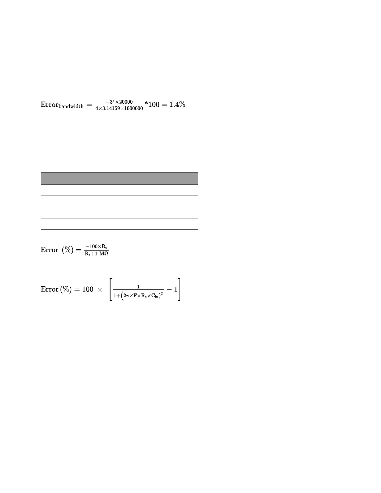
For low frequencies:
Additional error for high frequencies:
Where:
F = Input Frequency
R
s
= Source resistance
C
in
= Input capacitance (150 pF) + Cable capacitance
Use low-capacitance cable when measuring high frequency AC signals.
Low-Level AC Measurement Errors
When measuring AC voltages less than 100 mV, be aware that these measurements are especially sus-
ceptible to errors introduced by extraneous noise sources. An exposed test lead will act as an antenna and
the internal DMM will measure the signals received. The entire measurement path, including the power line,
act as a loop antenna. Circulating currents in the loop will create error voltages across any impedances in
series with the instrument’s input. For this reason, you should apply low-level AC voltages to the instrument
through shielded cables. You should also connect the shield to the input LO terminal.
Be sure to minimize the area of any ground loops that cannot be avoided. A high-impedance source is
more susceptible to noise pickup than a low-impedance source. You can reduce the high-frequency
Keysight DAQ970A User's Guide 201
4Measurement Tutorials