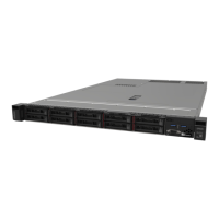
Chapter 2. Server components
This section includes information about the front view, rear view, and top view of the server. Front I/O
modules, the system board assembly and LEDs are also illustrated in detail.
Front view
Front views vary by models. Depending on the model, the server might look slightly different from the
illustrations in this topic.
Refer to the following front views for different server models:
•
“Server model with four 2.5-inch drive bays” on page 19
• “Server model with four 2.5-inch drive bays and a front adapter assembly” on page 20
• “Server model with eight 2.5-inch drive bays” on page 20
• “Server model with ten 2.5-inch drive bays” on page 21
• “Server model with no backplane” on page 22
Server model with four 2.5-inch drive bays
Table 6. Components on the front of the server
Callout Callout
1 Drive status LED 2 Drive activity LED
3 USB 3.2 Gen 1 (5Gbps) connector
4 Diagnostics panel
5 External LCD connector 6 USB 3.2 Gen 1 (5Gbps) connector
7 Mini DisplayPort connector
8 Rack latch (right)
9 Pull-out information tab
10 Drive bay filler (1)
11 Drive bays (4) 12 Rack latch (left)
Note: For more information about each component, see “Front components overview” on page 22.
© Copyright Lenovo 2024 19

 Loading...


