27.02.2014
2 3 112 851 en Additional page GMK 6400
Maximum
permitted load
The lashing eyelets, support points and locking points are designed for the
maximum forces listed below.
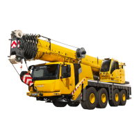
Lashing eyelets
The maximum forces permitted for the lashing
eyelets (1) are F1 and F2 in the direction indi-
cated.
Support points
The maximum force permitted for the support
points (2) is F3 in the angle range between the
horizontal (3) and vertical (4) axes.
F3 = max. 258 kN (58 000 lbf)
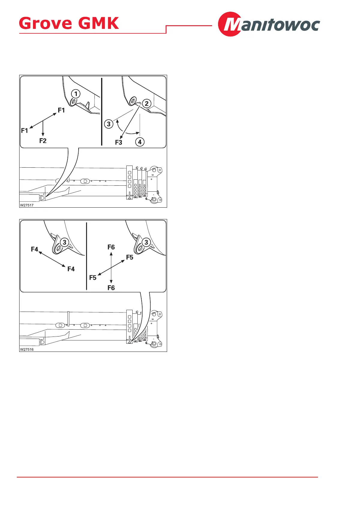
Locking points
The maximum forces permitted for the locking
points (3) are F4, F5 and F6 in the direction
indicated.
– Horizontally: F1 = max. 45 kN
(10 115 lbf)
– Vertically: F2 = max. 45 kN
(10 115 lbf)
– In the direction
of travel:
F4 = max. 65 kN
(14 600 lbf)
– Horizontally: F5 = max. 65 kN
(14 600 lbf)
– Vertically: F6 = max. 112 kN
(25 150 lbf)
 Loading...