Rigging work
12.6 Outriggers
12 - 36 3 112 993 en Operating manual GMK 6400
12.07.2013
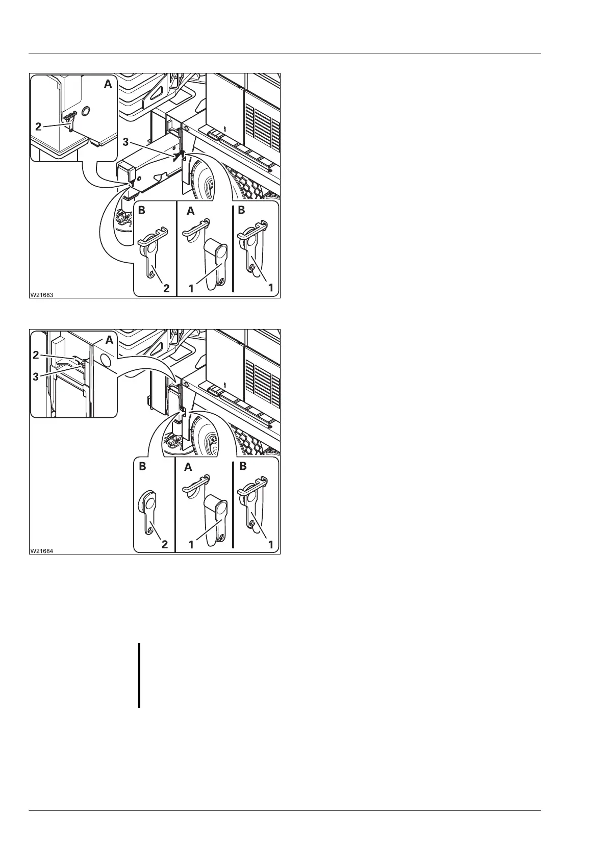
Outrigger span 8.70 x 5.00 m (28.5 x 16.4 ft)
(A) – Requirements
– Pin (1) is removed
– Pin (2) is inserted
(B) – Setting and securing
• Extend the outrigger beam up to the mark-
ing (3).
• Secure the outrigger beam with the pin (1).
• Pin (2) remains inserted.
• Set the outrigger span on the other outrig-
ger beam in the same way.
Outrigger span 8.70 x 2.71 m (28.5 x 8.9 ft)
(A) – Requirements
– Pin (1) is removed
– Pin (2) inserted in holder (3)
(B) – Setting and securing
• Completely retract the outrigger beam.
• Secure the outrigger beam with the pin (1)
and (2).
• Set the outrigger span on the other outrig-
ger beam in the same way.
For on-road
driving
• Set an outrigger span of 8.70 x 2.71 m (28.5 x 8.9 ft) on all outrigger beams
and secure them.
• Secure all the outrigger pads in the driving position; à p. 12 - 43.
G
Risk of accident if outriggers/outrigger pads are not secured
Always secure all retracted outrigger beams and all outrigger pads in the
driving position. Avoid serious accidents caused by outrigger beams/out-
rigger pads slipping out.
 Loading...