CSP−900RMM−2MD Helicopters, Inc.
Rotorcraft Maintenance Manual
Page 207
Original
21-20-00
1
2
3
4
5
6
7
8
9
12
13
14
15
18
16
17 (2 PL)
10
11
(6 PL)
(2 PL)
9G21−013
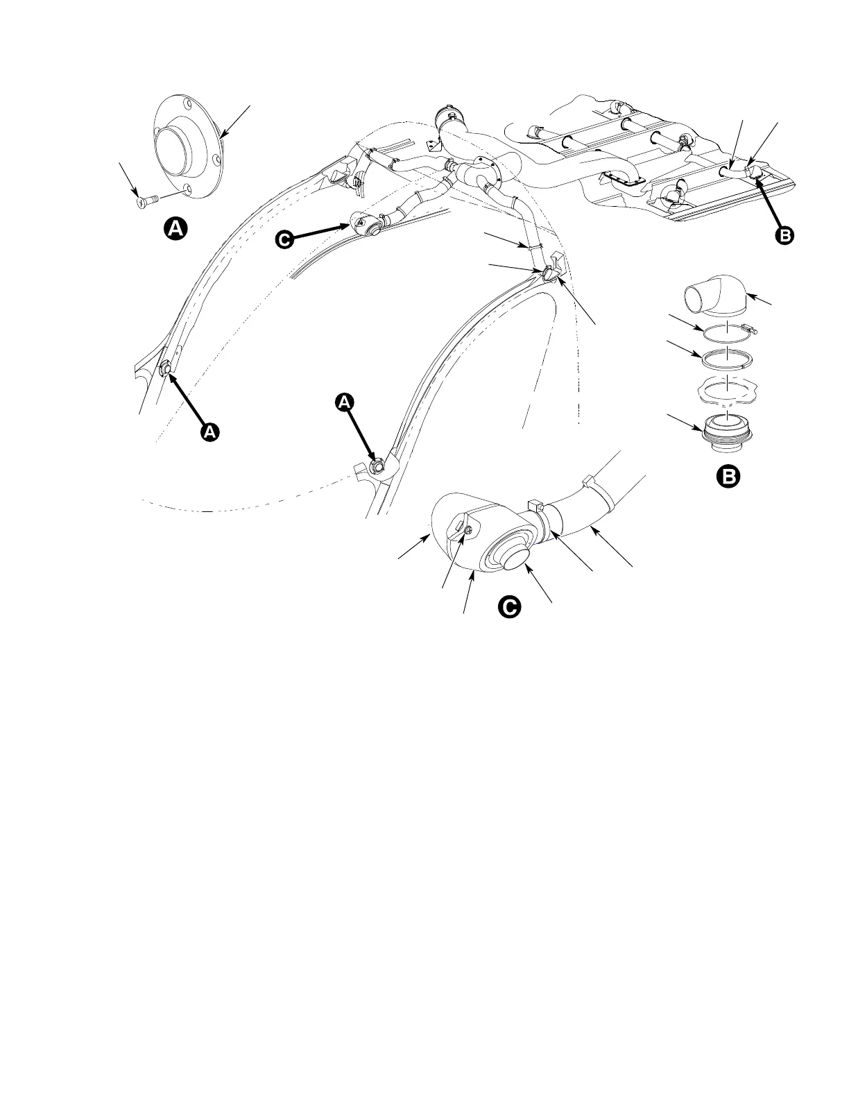
1. SCREW CROSSED RECESSED, FLAT
2. SIDE GASPER ASSEMBLY
3. HOSE CLAMP BAND TYPE
4. FLEXIBLE DUCT PLENUM−TO−GASPER
5. LH GASPER MOUNTING PLENUM
6. SCREW CROSSED RECESSED, PAN HEAD
7. WASHER, FLAT
8. RH GASPER MOUNTING PLENUM
9. OVERHEAD GASPER ASSEMBLY
10. CLAMP, BAND TYPE
11. FLEXIBLE DUCT AFT CABIN
12. GASPER ASSEMBLY PLENUM CAP
13. GASPER NUT
14. PASSENGER GASPER ASSEMBLY
15. PLENUM CAP CLAMP
16. CLAMP, BAND TYPE
17. DOOR PILLAR PLENUM
18. TIE−DOWN STRAP
Figure 205. Gasper Assemblies
5. Gasper Assembly Crew Station
A. Gasper Assembly (Crew Station)
Removal
(Ref. Figure 205)
NOTE: This task is typical for left and right
crew station gasper removal.
(1). Remove crew station side gasper
assembly by removing screws (1) from
side gasper (2) and remove gasper
assembly.
B. Gasper Assembly (Crew Station)
Installation
(Ref. Figure 205)
NOTE: This task is typical for left and right
crew station gasper installation.
(1). Install crew station side gasper assem
bly in door pillar with screws (1).
Torque screws (1).