CSP−900RMM−2MD Helicopters, Inc.
Rotorcraft Maintenance Manual
Page 609
Revision 35
32-00-00
9G32−024B
13
7
12
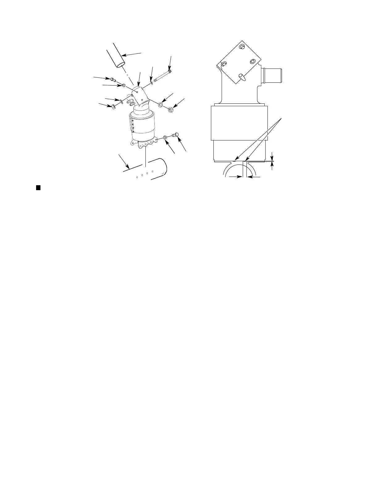
DRAIN PORTS (BOTH SIDES)
0.300 INCH (7.62 MM) APPROX
0.030 INCH (0.76 MM) APPROX
1
2
3
9
8
4
5
10
11
6
1. DAMPER (REF. IPL, 32−00−00, FIG. 2)
2. COUNTERSUNK WASHER
3. BOLT
4. FLAT WASHER
5. NUT
6. FLAT WASHER
7. BOLT
8. COUNTERSUNK WASHER
9. BOLT
10. FLAT WASHER
11. NUT
12. SKID TUBE
13. AFT CROSSTUBE
Figure 608. Damper Inspection
E. Landing Gear Damper Assembly
Inspection
(Ref. Figure 608)
(1). Examine dampers (1) for cracks, dents,
gouges, and corrosion.
(a). No cracks, dents, gouges, or corrosion
permitted.
(2). Examine dampers (1) for too much
leakage.
(a). Too much leakage not permitted.
(3). Examine dampers (1) for missing nuts
(5, 11), bolts (3, 7, 9), and washers (2, 4,
6, 8, 10).
(a). Replace missing nuts (5, 11), bolts (3,
7, 9), and washers (2, 4, 6, 8, 10).
(4). Make sure there is a clearance between
damper cover and inner cover.
(a). Replace damper (1) if there is binding
or interference.
(5). Examine mating surfaces of dampers
(1) and skid tubes (12) for damage,
deformation, and corrosion.
(a). No damage deformation, or corrosion
permitted.
(6). Examine mating surfaces of dampers
(1) and aft crosstube (13) for damage,
deformation, or corrosion.
(a). No damage deformation, or corrosion
permitted.
(7). Examine 4 drain ports of damper (1) for
blockage.
(a). No blockage permitted.