CSP−900RMM−2 MD Helicopters, Inc.
Rotorcraft Maintenance Manual
Page 2
Revision 34
32-00-00
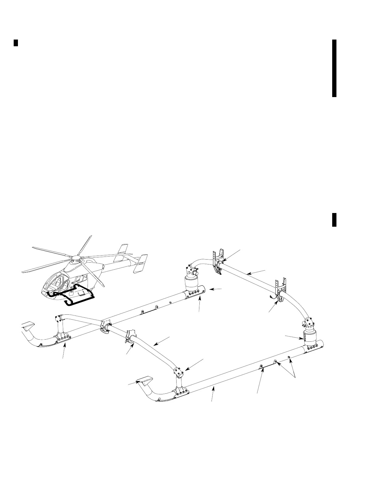
F. Landing Gear Damper Assemblies
The landing gear damper assemblies are
bidirectional hydraulic units that attach to the
aft crosstube assembly and skid tubes. The
damper assemblies secure the skid tubes to
the crosstube assembly while transferring
landing loads from the skid tubes to the
crosstube assembly. The dampers also dissi
pate landing gear-to-ground resonance
oscillations and absorb vertical shock loads
during landings.
Each damper is an aluminum alloy housing
with an internal bidirectional hydraulic
metering circuit. The damping rate of the unit
is controlled by forcing fluid from one side of
the internal damper piston to the other side of
the internal piston head. An internal bidirec
tional fixed orifice is housed in the piston head
to meter the damping rate. The damper
incorporates an integral reservoir to supply
compensation for thermal expansion and fluid
leakage.
The reservoir fluid level indicator (1) is a
rotating shaft which shows through a 120 pie
shaped window. When the reservoir is filled,
the window shows green with a very thin
wedge of red showing to the first notch (2) on
the housing. The thin wedge of red shows the
reservoir is not completely full, to allow for
fluid expansion.
G. Skid Tubes
The skid tubes are 7075 T6 aluminum alloy
tubes that are attached to the forward and aft
crosstube assemblies by the forward spacer
fittings and damper assemblies. The skid
tubes provide a ground contact point for the
landing gear. Each skid tube has a forward,
middle and aft steel abrasion strip that
protects the skid tubes during landing.
The middle of the skid provides a fixed
bushing/pin location for use of the ground
handling wheels during ground operations. A
crew station access step is located on the top of
each skid tube. The access step provides a 4 by
8 inch (10 by 20 cm) non-slip step area.
SKID TUBE
FORWARD
SPACER FITTING
AFT
SADDLE ASSEMBLY
AFT
CROSSTUBE
SIDE STOP
CLAMP ASSEMBLY
PLUG
DAMPER
ASSEMBLY
AFT
ABRASION STRIP
FORWARD
CROSSTUBE
FORWARD
SADDLE ASSEMBLY
STEP
FORWARD
ABRASION STRIP
9G32-001
GROUND HANDLING
ATTACH POINTS
MID ABRASION
STRIP
Figure 1. Landing Gear Assembly