CSP−900RMM−2 MD Helicopters, Inc.
Rotorcraft Maintenance Manual
Page 208
Revision 35
18-00-00
9G18-005C
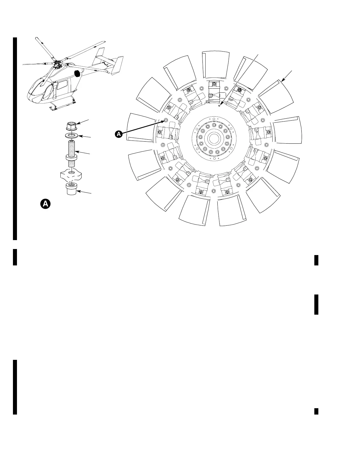
VIEW LOOKING FORWARD
13
12
11
10
9
8
7
6
5
4
3
2
1
BALANCE STUD ASSEMBLY
(13 PL, TYP)
5
4
2
6
1
3
1. ANTI−TORQUE FAN (REF. IPL, 64−30−01, FIG. 1)
2. BALANCE STUD
3. COLLAR
4. BALANCE WEIGHTS
5. NUT
6. AZIMUTH SENSOR INTERRUPTER RIVET
Figure 205. Anti−Torque Fan Balance Weight Adjustment
B. Anti−Torque Fan Balance Weight Change
(Ref. Figure 205)
(1). Remove baggage compartment closeout
panels and soft insulation panels (ref
Section 25-50-00).
(2). Remove anti-torque fan diffuser lower
half (ref. Section 53-00-00).
(3). Number balance studs (2) on anti-
torque fan (1) with a permanent
marker (ref. Figure 205).
(4). Add or remove balance weights (4) (ref.
Table 201) recorded from the NOTAR
Balance Solutions Menu Procedure (ref.
CSP-900RMM-3, Section 95-30-00).
NOTE:
Thickness of balance weights (4) on bal
ance stud (1) cannot be more than 0.20
inch (5.1 mm).
One gram of balance weight change gives
approximately 0.18 IPS of balance
change.
If more than three weights are added at
one time, weigh the total number of
weights with a scale.
(a). Remove nut (5).
(b). Remove or install balance weights
(4), as necessary.
(c). Install nut (5) on balance stud (2).