CSP−900RMM−2 MD Helicopters, Inc.
Rotorcraft Maintenance Manual
Page 206
Revision 4
26-10-20
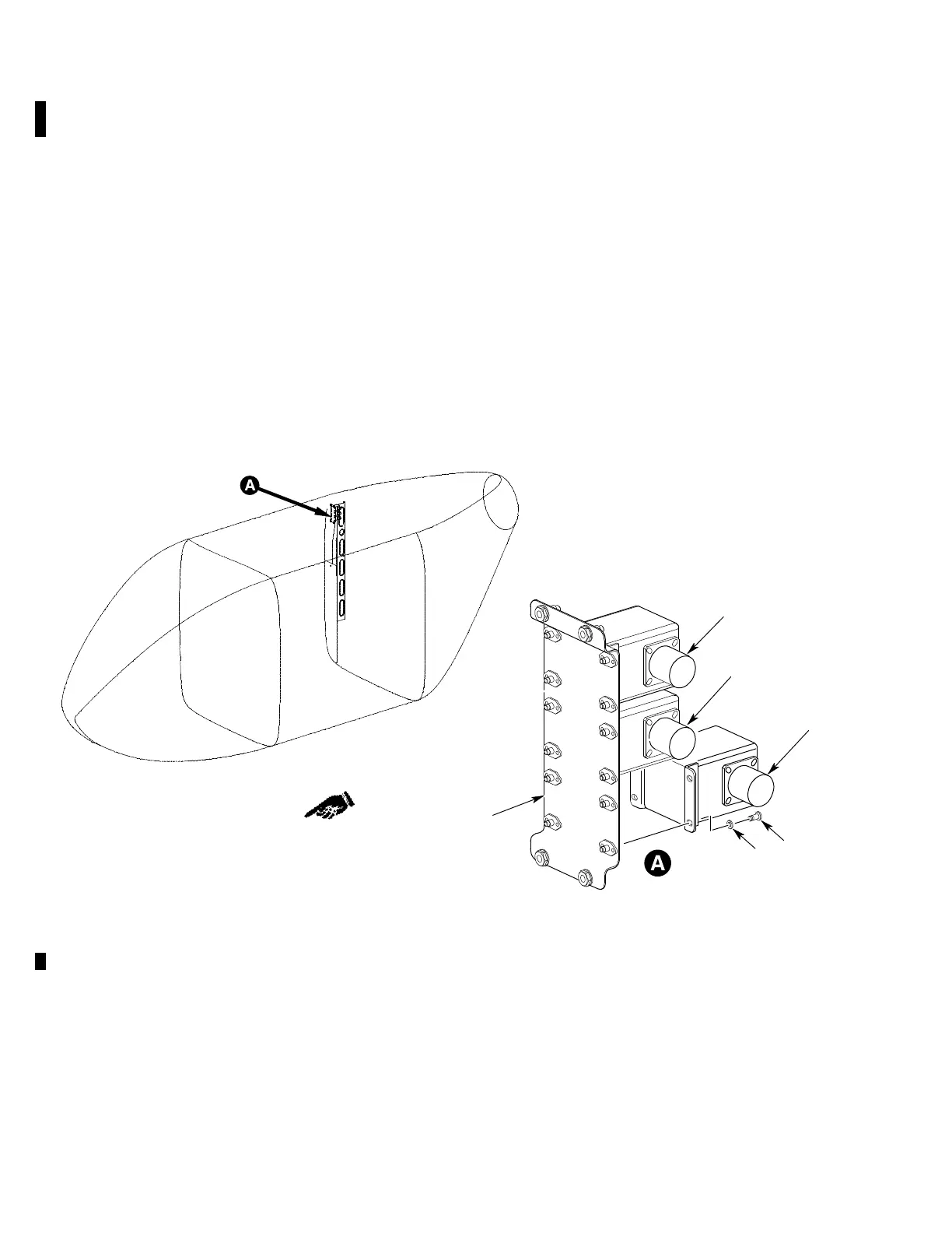
4. Deck and Engine Fire/Overheat Control
(Typical)
(Ref. Figure 203)
A. Fire/Overheat Control Unit Removal
(1). Remove right aft cabin passenger seat,
if installed (Ref. Section 25-20-00).
(2). Remove right aft cabin interior trim
panel (Ref Section 25-20-00).
(3). Detach electrical connector transmis
sion deck P370 (2), left engine P371 (3),
or right engine P372 (1), from fire/over
heat control unit.
(4). Remove screws (5) and washers (6), and
remove control from bracket assembly
(4).
B. Fire/Overheat Control Unit Installation
(1). Install control on bracket assembly
with screws and washers. Torque
screws.
(2). Attach electrical connector transmis
sion deck P370, left engine P371, or
right engine P372 to fire/overheat
control.
(3). Install right aft cabin interior trim
panel (Ref Section 25-20-00).
(4). Install right aft cabin passenger seat
(Ref. Section 25-20-00).
1
2
5
6
4
3
9G26−003A
NOTE: THE UPPER DECK AND ENGINES FIRE/OVERHEAT DETECTION CIRCUITS
ARE CONNECTOR DEPENDANT AND ARE NOT CONTROL UNIT INDEPENDENT
1. RIGHT ENGINE FIRE/OVERHEAT CONTROL (P372)
2. TRANS. DECK FIRE/OVERHEAT CONTROL (P370)
3. LEFT ENGINE FIRE/OVERHEAT CONTROL (P371)
4. MOUNTING BRACKET ASSEMBLY
5. SCREW
6. WASHER
Figure 203. Deck and Engine Fire/Overheat Control Units