CSP−900RMM−2 MD Helicopters, Inc.
Rotorcraft Maintenance Manual
Page 802
Revision 35
32-00-00
9G32−025B
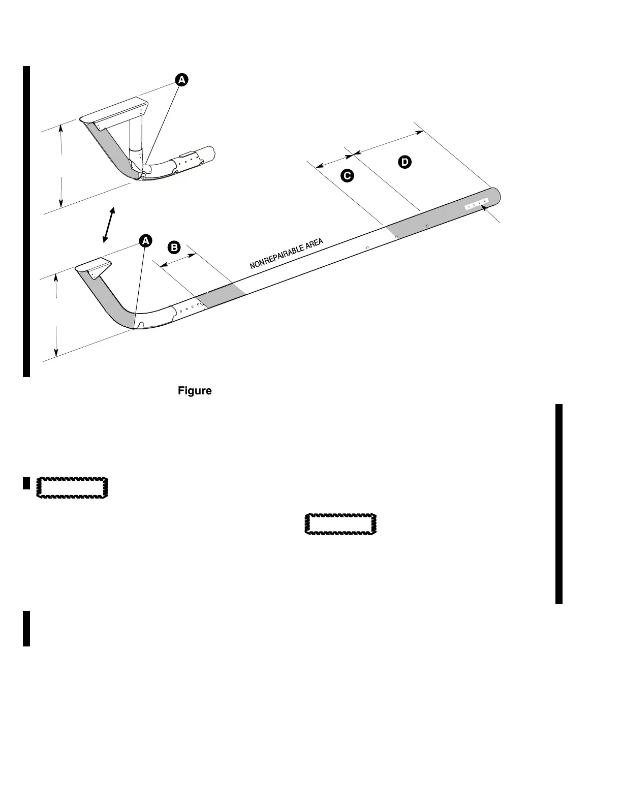
18.5 INCH
(46.99 CM)
10 INCH
(25.40 CM)
12 INCH
(30.48 CM)
13 INCH
(33.02 CM)
DAMPER BOLT HOLE
(8 PL)
RIGHT SIDE TYPICAL
LEFT SIDE SHOWN
OPTIONAL SKID TUBE STEP
13 INCH
(33.02 CM)
Figure 802. Skid Tube Repairable Sections
2. Left−Hand and Right−Hand Skid Tube
Assemblies
A. Blend Repair
(Ref. Figure 802)
Do not remove material or do
the blend repair more than once
on a surface.
(1). Blend out nicks, scratches, or corrosion
in repairable sections A, B, C, and D
(ref. CSP-SPM, Section 20-40-00,
Mechanical Defects).
NOTE: Material removal and repair procedure
can be done one time only on a surface.
(a). Material removed from the surface of
Section A cannot be deeper than
0.010 inch (0.25 mm).
(b). Material removed from the surface of
Section B cannot be deeper than
0.010 inch (0.25 mm).
(c). Material removed from the surface of
Section C cannot be deeper than
0.025 inch (0.64 mm).
Do not remove material in Sec
tion D adjacent to the bolt holes
for the landing gear damper assembly.
(d). Material removed from the surface of
Section D cannot be deeper than
0.040 inch (1.02 mm).
(2). Refinish the blended area (ref. CSP-
SPM, Section 20-30-00).
CAUTION
CAUTION