CSP−900RMM−2 MD Helicopters, Inc.
Rotorcraft Maintenance Manual
Page 102
Revision 19
28-10-00
Table 101. Troubleshooting (Cont.)
Fault Ref. SectionCorrective ActionProbable Cause
Fuel quantity indicator
indicates EMPTY when fuel
is in supplemental fuel tank
Faulty wiring between
quantity transmitter and
quantity indicator
Test and repair wiring 98−00−00
Faulty wiring between AUX
FUEL XMIT circuit breaker
and indicator
Test and repair wiring 98−00−00
Faulty indicator Replace indicator 95−00−00
Faulty transmitter Replace transmitter 28−10−00
Fuel quantity indicator
indicates inaccurately
Faulty transmitter Replace transmitter 28−10−00
Faulty indicator Replace indicator 95−00−00
Uncommanded fuel transfer
from supplemental to main
tank
Check valve not installed in
suppelmental tank
Install check valve 28−10−00
Faulty check valve in
supplemental tank
Replace replace check valve 28−10−00
D A
9G28-069A
DS2 SP1
SEND
INSTRUMENT PANEL
AUX FUEL QTY
IND LT
A620
ELECTRICAL LOAD CENTER
C
FUEL XFER PUMP
INDICATOR LT
ON
3
AUX
FUEL XMIT
CB33
AUX
FUEL
CB61
1A
5A
J2
52
46
P374
E
SI
OFF
1
AUX FUEL
XFER
DSI
-
+
A
B
E
E
GS300-A
GS300-B
(+) 28VDC
(-) GRD
M PUMP MTR
A310
AUX FUEL PUMP
P537 J1
CENTER CONSOLE
DS2
-
+
IGN (+ 28VDC)
GROUND (-)
AUX FUEL QTY
IND
53
40
54
55
P118 J118
E E
TB3-1
TB2-9
(+) 28VDC
(-) GROUND
A612
FWD INTERCON PANEL
A311
AUX FUEL QTY TRANSMITTER
BCEFGH
NOTE 1
BATT BUS 4
GS110-A
GS109-E GS300-C
NOTE: WIRE BETWEEN TB3-1A AND TB2-9H MAY BE DIFFERENT, DEPENDING ON OTHER INSTALLATIONS
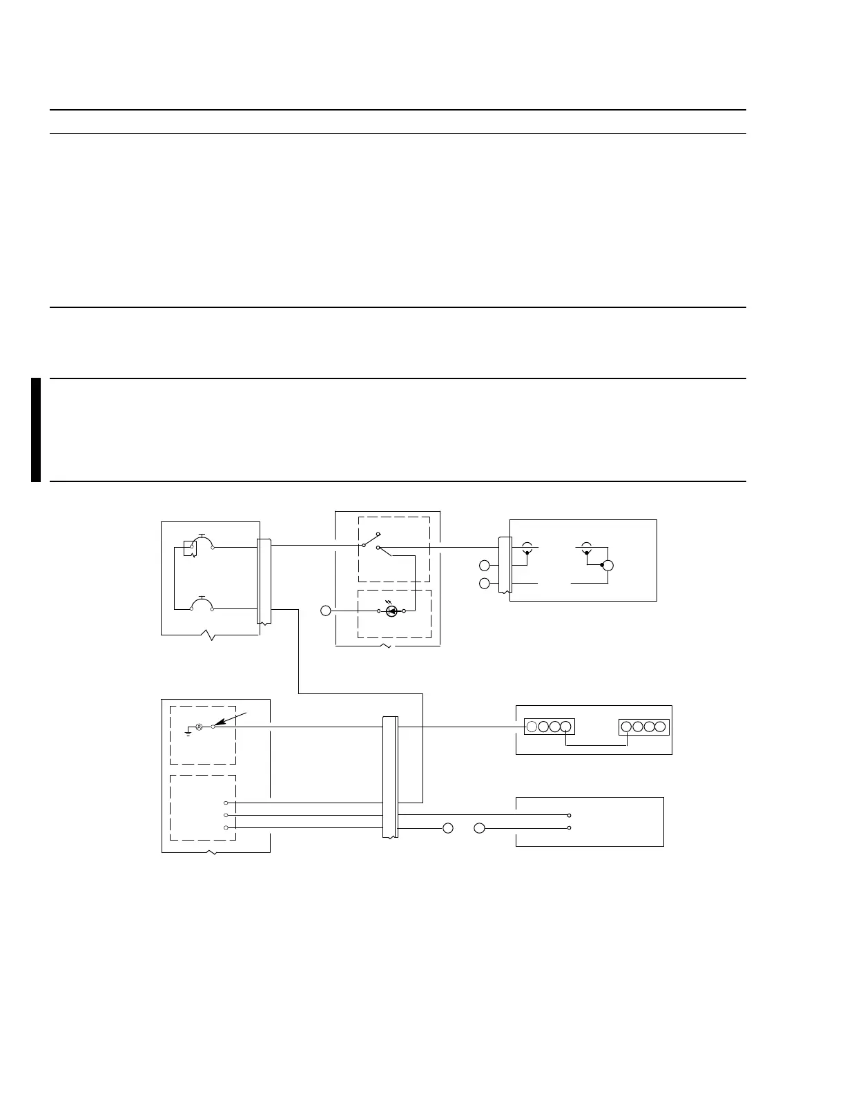
Figure 101. Supplemental Fuel System Wiring Diagram
 Loading...


