Do you have a question about the Metcom Solutions MCS301 and is the answer not in the manual?
Defines key terms and abbreviations used in the manual for clear understanding of technical content.
Details the IEC and MID standards the MCS301 meter has been tested and approved against.
Provides critical safety regulations for installation, handling, and operation to prevent hazards.
Outlines the maintenance requirements, cleaning guidelines, and disposal procedures for the meter.
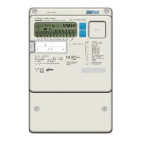
Illustrates and labels the components visible on the front of the MCS301 meter.
Provides detailed physical dimensions and drawings of the meter's external structure.
Describes the various parts of the meter's case, including terminal blocks and covers.
Details the different types of seals used on the meter for security and integrity.
Explains the information printed on the meter's nameplate, such as serial number and ratings.
Describes the format, size, and elements of the meter's liquid crystal display.
Explains the different operating modes for the display and how to navigate them using buttons.
Details the standard display function, measured values in rolling mode, and list parameters.
Covers alternate mode (A-button) and reset mode (R-button) with supported options.
Describes the function of the optical sensor for activating the display when buttons are inaccessible.
Explains the meter's measurement principle using ASIC and DSP for accurate data processing.
Details the calculation methods for voltage, current, active, reactive, apparent demand, and harmonics.
Describes the standard vectorial, absolute, and arithmetic measuring methods used by the meter.
Lists supported energy registers, including 3ph values, tariffs, and OBIS codes.
Details the characteristics of demand measurement, types, tariffs, and configurable periods.
Provides lists of instantaneous demand and PQ data, including values with and without harmonics.
Describes how average, minimum, and maximum values are calculated and stored over defined intervals.
Explains the difference between secondary and primary measurements considering CT/VT ratios.
Explains system title, logical device name, and utility device ID based on DLMS/COSEM model.
Describes meter registration at HES using system title and data notification service.
Details the activity calendar and special day table for defining tariff programs.
Explains the real-time clock characteristics, battery backup, and time synchronization.
Covers Gregorian and Iranian calendars, and DST time change configurations.
Defines configurable sources for ending billing periods and demand resets.
Describes meter behavior after a demand reset, including historical data storage.
Details the storage of historical data for energy and demand registers at end of billing.
Explains the meter's data model and identification system using OBIS and IDIS.
Details the supported communication protocols like DLMS and EN62056-21.
Describes the common structure of load profiles, including timestamps, status, and values.
Specifies characteristics of Load Profile 1, including configurable interval and selectable quantities.
Details the configuration and data for Load Profile 2, designed for daily energy recording.
Outlines the characteristics of Load Profile 3 for storing average values of parameters.
Specifies the configuration for Load Profile 4, which captures maximum values of parameters.
Details the configuration of Load Profile 5 for capturing minimum values of parameters.
Explains Load Profile 6 for capturing harmonics and Total Harmonic Distortion (THD) data.
Describes snapshot profiles for instantaneous PQ and energy values via optical port.
Details Load Profiles 7-10 designed for use with up to 4 M-Bus meters.
Lists the 7 main groups of events supported by the meter, including Standard, Fraud, and Power Quality logs.
Describes the alarm handling process involving registers, filtering, descriptors, and sending.
Details the events recorded in the Standard Event Log, including power events and parameter changes.
Explains events related to fraud detection, such as terminal cover removal and magnetic field detection.
Lists events related to the disconnector's status, including manual, remote, and limiter threshold actions.
Details events related to power quality issues like undervoltage, overvoltage, and phase asymmetry.
Records events related to communication module status, GPRS registration, and connections.
Logs events related to power failures, including duration and phase-specific interruptions.
Stores special events and total active energy consumption related data.
Records events related to M-Bus communication, device installation, and errors.
Explains how average voltage per phase is determined and stored according to COSEM objects.
Details the meter's detection of under and overvoltage events, including thresholds and parameters.
Describes the detection of voltage cuts (power outages) based on threshold and time parameters.
Covers the meter's capability to measure harmonics up to 15th and THD up to 32th.
Explains the condition of unbalanced load and how it's detected based on current deviations.
Details the monitoring of voltage unbalance and its detection criteria.
Defines indicators for slow voltage variation (W1), THD (W2), voltage unbalance (W3), and flicker (W4).
Categorizes power failures into short, long, and power down types.
Details counters for short and long power failures across all phases and individual phases.
Stores the duration of the last long power failure in all phases and individual phases.
Contains events related to long power outages, including timestamps, durations, and event codes.
Lists parameters that can be changed depending on access rights, such as demand registers and thresholds.
Details global key parameters related to authentication and encryption for meter security.
Describes various communication interfaces like Optical, M-Bus, RS485, RS232, and Ethernet.
Details the meter's control and pulse inputs, including their assignment and electrical characteristics.
Explains the electronic and mechanical relay outputs, their assignments, and overload control features.
Describes the RJ12 connector, pin assignments, and physical interface for customer connection.
Specifies the protocol and data transfer format for the P1 port based on EN62056-21 Mode D.
Explains data security (encryption/authentication) for CII communication via IDIS package 2.
Details remote, manual, and schedule-based control of the load control relay.
Explains disconnect control via load limitation in normal and emergency operations.
Describes the alarm and fatal error registers, including bit assignments for various errors.
Details features like terminal/main cover detection, magnetic field detection, and anti-creep.
Covers password protection (LLS), high-level security (HLS), and HW jumper protection.
Outlines the main steps of FW upgrade: Initial Phase, Image Transfer, Check, and Activation.
Explains how to identify active firmware versions using COSEM objects.
Describes M-Bus interface support, master functionality, and wired M-BUS definitions.
Details device IDs for M-Bus meters and the meter's M-Bus profile features.
Covers M-Bus event codes, alarm registers, and status information.
Explains the process of installing M-Bus devices, including scanning and addressing.
Details GPRS interface, IP network addressing, and communication services.
Explains the push process involving triggering objects, script tables, and setup configurations.
Describes time synchronization using an NTP server in combination with COM200 module.
Describes Public, Pre-established, Management, and Reading clients and their SAPs.
Outlines policies for establishing parallel associations across different communication ports.
States that factory calibration is done and outlines preconditions for accuracy testing.
Explains how to enter a special test mode for reducing test durations.
Describes how to perform and view results of creep and anti-creep tests on the display or LED.
Details mechanical installation and initial power-up checks, including phase voltage indication.
Describes how to test meter functions like scroll mode, display check, and phase failure indication.
Provides recommendations for fuse protection in low voltage applications.
Explains the type key structure for hardware versions up to V1.3, detailing configuration options.
Details the type key structure for hardware versions from V1.5 onwards.
Shows the complete connection diagram including main and auxiliary connections.
Illustrates mains connection diagrams for different configurations (4-wire, 3-wire, CT).
| Brand | Metcom Solutions |
|---|---|
| Model | MCS301 |
| Category | Measuring Instruments |
| Language | English |