1-4
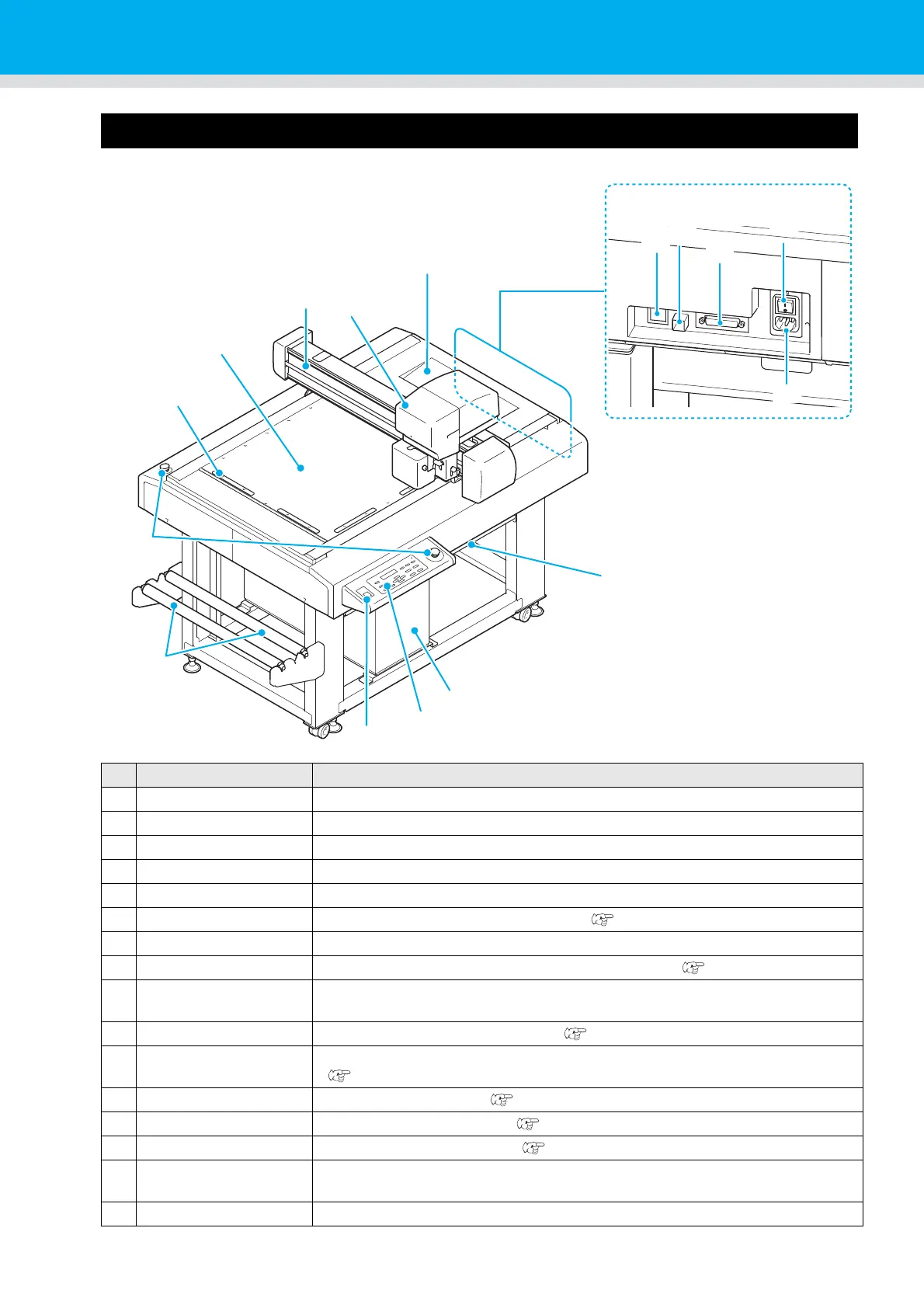
Names and Functions of Parts
Main Unit
Name Function
(1) Y bar Moves the head in the Y direction.
(2) Head Holds a variety of tools. The mountable tool depends on the head.
(3) Tray Small tools, such as a retractable knife and other cutters, can be placed on.
(4) Table Can put temporarily the workpiece and finished product.
(5) Vacuum Unit Provides vacuum adhesion of the workpiece on the cutting panel.
(6) Operation panel Makes the settings required for the unit. ( P.1-6)
(7) Power switch Turns the unit power ON / OFF.
(8) Roll bar Set the roll of adsorption sheet on top of the two bars. ( P.2-9)
(9)
EMERGENCY switch
Press in the event of an emergency. The power is forcibly cut to stop unit
operation.
(10) Set guide plates Guides for mounting the workpiece. ( P.1-9)
(11)
Cutting panel / Felt mat
Holds the workpiece. It offers a regular array of small holes for vacuum adhesion.
(P.1-9)
(12) LAN connector LAN interface connector ( P.1-7)
(13) USB interface USB 2.0 interface connector ( P.1-7)
(14) RS-232C interface RS-232C interface connector ( P.1-7)
(15)
Main power switch
Turns the unit power ON / OFF. Normally, leave ON. Turn OFF when doing
maintenance.
(16) Power inlet Connector for the plotter power cable.
(1)
(6)
(7)
(9)
(10)
(11)
(12)
(13)
(14)
(15)
(16)
(4)
(5)
(2)
(3)
(8)